Lower flex circuit assembly, Lower, Flex – IBM BladeCenter T Type 8720 User Manual
Page 82: Circuit, Assembly
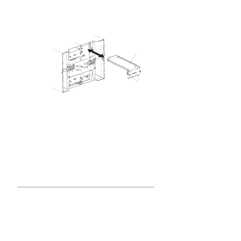
Upper flex circuit assembly
Captive fasteners
7.
Carefully
remove
the
old
upper
flex
circuit
assembly
by
placing
your
fingers
under
the
lower
edge
of
the
assembly
and
pulling
the
unit
out
of
the
chassis.
8.
Remove
the
new
upper
flex
circuit
assembly
from
the
packaging.
9.
Align
the
assembly
so
that
the
stamped
position
identifier
″Top″
is
facing
you.
10.
Position
the
front
end
of
the
new
upper
flex
circuit
assembly
into
the
assembly
bay
in
the
chassis,
making
sure
the
leading
edge
rests
on
the
lower
shelf
of
the
bay.
CAUTION:
Be
careful
not
to
damage
the
EMI
gaskets
located
on
the
vertical
sides
of
the
upper
flex
circuit
assembly
bay.
11.
Carefully
push
the
assembly
all
the
way
into
the
bay.
12.
Using
a
screwdriver,
tighten
the
two
captive
fasteners
on
the
new
upper
flex
circuit
assembly.
Note:
Torque
the
screws
to
8
inch-pounds.
13.
Reinstall
the
I/O
switch
that
you
removed.
14.
If
you
have
no
other
replacement
procedures
to
perform
at
the
rear
of
the
system,
re-install
the
LAN
module
(see
and
the
KVM
module
(see
15.
Reconnect
the
power
to
the
system
(see
16.
For
Type
8720
systems,
reinstall
dc
terminal
covers.
17.
Start
up
the
system
(see
Lower
flex
circuit
assembly
Complete
the
following
steps
to
replace
the
lower
flex
circuit
assembly.
Note:
v
Read
v
Read
the
safety
notices
at
″Safety
information
″
on
page
v
Read
1.
Shut
down
the
system
and
remove
power
from
the
system
(see
72
BladeCenter
T
Type
8720
and
8730:
Hardware
Maintenance
Manual
and
Troubleshooting
Guide