1 system configuration example, 2 hardware connection diagram, System configuration – MITSUBISHI ELECTRIC PAC-YG31CDA User Manual
Page 8
3.System Configuration
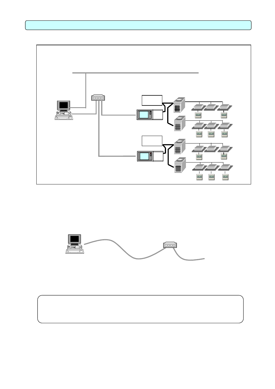
3.1 System Configuration Example
Power
supply unit
G-50A
G-50A
[Image drawing]
Indoor unit
Outdoor unit
LAN
HUB
BACnet IF
Software
Power
supply unit
Remote
controller
3.2 Hardware Connection Diagram
(1) LAN connection
Connect the LAN cable to the PC. The location of the LAN connector of the PC, refer to the
Instruction Manual of the PC.
To G-50A
LAN
10BASE-T
straight cable
HUB
BACnet IF
Software
Note:
• Be sure to use the HUB.
• Execute the LAN cascade connection as shown below.
For 10BASE-T, the cascade connection is executable up to a maximum of 4 stages.
5