The smart cat5 system configuration, The smart cat5 models, Smart – Minicom Advanced Systems CAT5 User Manual
Page 6: Smart cat5 switch, Figure 1 the smart cat5 system configuration, Figure 2 smart cat5 front panel, Figure 3 smart cat5 16 port rear panel, Mi n i co m, Computer 1, Computer 16 ricc ricc
SMART CAT5 SWITCH
5
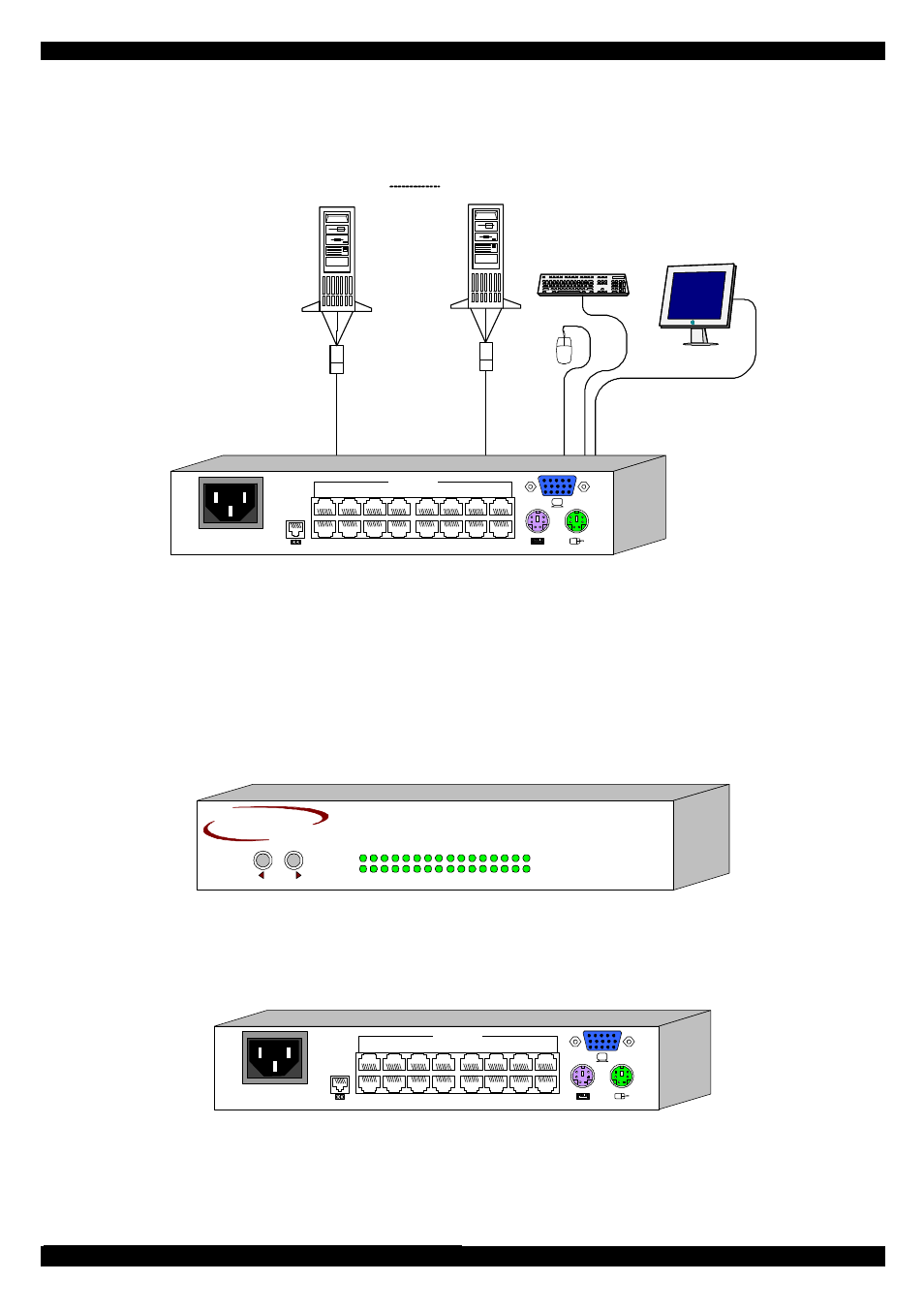
6. The Smart CAT5 system configuration
Figure 1 illustrates the basic configuration of the Smart CAT5 system.
Computer 1
Smart CAT5 Switch
Computer 16
RICC
RICC
POWER
100-250 VAC 50/60 Hz
1
2
3
4
5
6
7
8
10
11
12
13
14
15
16
9
COMPUTER
w
w
w
.m
in
ic
o
m
.c
om
Figure 1 The Smart CAT5 system configuration
7. The Smart CAT5 models
Figure 2 illustrates the front panel of the Smart CAT5 16 port model. The 8 port
model is the same but with only 8 columns of LEDs.
SMART
SELECT
CAT5
S W I T C H
MI N I CO M
10 11 12 13 14 15 16
1
2
3
4
5
6
7
8
9
Selected
CPU on
Figure 2 Smart CAT5 front panel
The figure below illustrates the rear panel of the Smart CAT5 16 port unit. The 8 port
model is the same but with only 8 Computer ports.
POWER
100-250 VAC 50/60 Hz
1
2
3
4
5
6
7
8
10
11
12
13
14
15
16
9
COMPUTER
w
w
w
.m
in
ic
o
m
.c
om
Figure 3 Smart CAT5 16 port rear panel