Installing faceplate/ handwheel – Grizzly G0694 User Manual
Page 26
-24-
Model G0694 (Mfg. Since 10/09)
3. rotate the spindle by hand until the lock pin
engages and keeps the spindle from rotat-
ing.
4. apply a thin coat of light machine oil on the
spindle threads, then thread the faceplate or
handwheel onto the spindle until it is snug.
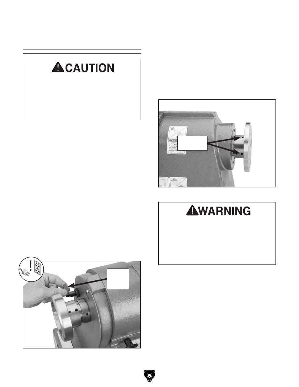
5. tighten the four faceplate or handwheel set
screws just behind the faceplate to secure it
to the spindle (see
figure 20).
To prevent the workpiece from flying off dur-
ing operation, the faceplate MUST be firmly
threaded onto the spindle and secured in
place by fully tightening the four faceplate
set screws. If these instructions are not
properly performed, serious personal injury
could occur.
6. Move the spindle lock lever from the six
o'clock locked position to the twelve o'clock
unlocked position.
Removing faceplate or Handwheel
apply the spindle lock, loosen the four set screws,
and unthread the faceplate or handwheel.
Installing faceplate/
Handwheel
the faceplate can be mounted on the outboard
side of the lathe for turning workpieces larger than
20" in diameter. in this case, the handwheel is
mounted on the inboard side.
to mount a workpiece to the faceplate, refer to
faceplate Turning on Page 30.
Tools Needed
Qty
t-handle hex Wrench 3mm .............................. 1
Installing faceplate or Handwheel
1. disConneCt Lathe FroM poWer!
2. pull the spindle lock lever out, then rotate
it from the twelve o'clock unlocked posi-
tion to the six o'clock locked position (see
figure 19).
Always disconnect the lathe from power
before using the spindle lock feature. Never
resume turning operations without making
sure that the spindle lock is disengaged and
the spindle turns freely by hand. Otherwise
personal injury or property damage could
result.
figure 19. Using the spindle lock lever.
spindle
Lock
Lever
figure 20. headstock faceplate set screw.
Faceplate
set screws