Chapter 2 configuration and connections, 1 debug board configuration – Freescale Semiconductor i.MX27 PDK 1.0 User Manual
Page 12
Freescale Semiconductor
i.MX27 PDK 1.0 Hardware User's Guide, Rev. 1.0 2-1
Chapter 2
Configuration and Connections
This section contains configuration information, connection descriptions, and other operational information
that may be useful during the development process.
2.1 Debug Board Configuration
The Debug board provides an easy, familiar interface for programming and debugging the i.MX
development systems and reference platforms.
This section describes the switches and connectors on the top of the Debug board, and the connector to the
CPU Engine board on the bottom of the Debug board. The Debug board is a small card that you can insert
or remove from the platform. The ability to remove the debug board is a major advantage to marketing and
sales teams who want to demonstrate and showcase a variety of products and ideas in a streamlined, near
form factor way, without the added software development bulk.
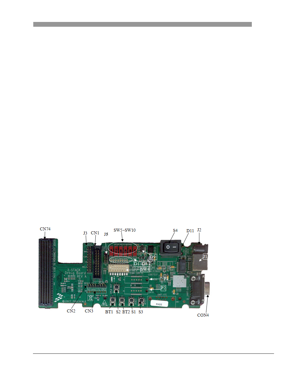
2.1.1
Debug Board Top Switches and Connectors
Figure 2-1 identifies the switches and connectors located on top of the Debug board. Table 2-1 describes
the switches and connectors.
.
Figure 2-1 Debug Board, Top View