Foundry Networks AR1202 User Manual
Page 46
Foundry AR-Series AR1202 and AR1204 Installation Guide
A - 6
© 2004 Foundry Networks, Inc.
June 2004
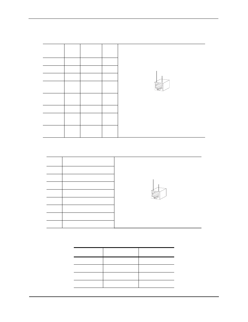
Table A.8: Pinouts: Ethernet Cable (RJ-45)
Foundry
Pin
Signal
Direction
LAN
Signal
1
TxD+
—>
TxD+
2
TxD–
—>
TxD–
3
RxD+
<—
RxD+
4
not
used
not
used
5
not
used
not
used
6
RxD–
<—
RxD–
7
not
used
not
used
8
not
used
not
used
Table A.9: Pinouts: WAN Cable (RJ-48C)
Pin
Signal
1
receive from network ring (R)
2
receive from network tip (T)
3
no connection
4
send toward network ring (R)
5
send toward network TIP (T)
6
not used
7
not used
8
not used
Table A.10: DB-25 to RJ-45 Modem Adapter Pinouts
RJ-45 Pin
Signal
DB-25 Pin
1
no connection
-
2
no connection
-
3
RxD
3
4
Ground
7
Pin 8
Pin 1
Pin 8
Pin 1