Network connections, Connecting the wan cable, Etwork – Foundry Networks AR1202 User Manual
Page 26: Onnections, Onnecting, Wan c, Able
Foundry AR-Series AR1202 and AR1204 Installation Guide
3 - 8
© 2004 Foundry Networks, Inc.
June 2004
8.
Engage and tighten the captive screw on the cable retainer bracket in the threaded hole adjacent to the DC
input jack on the router.
9.
Coil the excess cable and secure it on the tray behind the router.
10. Mount the tray in the equipment rack using either four (provided) Phillips pan head 10-24 x .5 inch screws or
four (provided) Phillips pan head 12-32 x .5 inch screws, whichever fits the equipment rack.
11. Connect the network cables to the router. Secure the cables in the clips located on the bottom of the carriage
assembly. Refer to “Network Connections” on page 3-8.
12. Connect the appropriate ends of the AC cord to the secured power supply and a 110/120 VAC outlet.
13. Using a small flat blade screwdriver, engage and tighten the captive screw to secure the carriage assembly to
the rack tray.
Network Connections
The following sections describe how to connect various network cables to the Foundry AR1202 and AR1204
router.
Connecting the Ethernet Cable
The front panel on the router accommodates one LAN connections. Use a category 5, twisted-pair Ethernet cable
with RJ-45 connectors to connect to the LAN. Refer to Figure 3.2 on page 3-2 to identify this cable.
Follow this procedure to connect the AR1202 and AR1204 to an Ethernet LAN network.
1.
Connect the RJ-45 connector of a category 5 rated Ethernet cable to either the Ethernet 0 port on the back
panel.
2.
Connect the RJ-45 connector on the other end of the cable to the LAN port.
Make sure that the cable connectors are locked and secure in the ports. See Table A.8 on page A-6 for pinout
information about this cable.
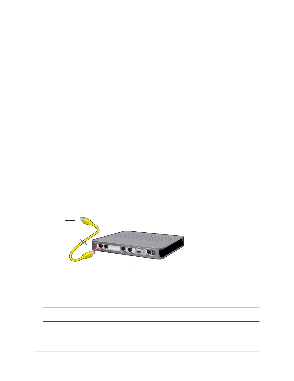
Figure 3.11
Connecting the Ethernet Cable
Connecting the WAN Cable
The back panel accommodates up to two WAN (model specific) cables. Use 26 AWG (minimum) category 5,
twisted-pair cable with RJ-48C connectors for this interface. Refer to Figure 3.3 on page 3-2 to identify this cable.
CAUTION:
To reduce the risk of fire, use only number 26 AWG or larger UL Listed or CSA Certified Telecommu-
nication Line Cord for all network connections.
Follow this procedure to connect a WAN port to the network:
1.
Insert the RJ-48C connectors on one end of one cable in the appropriate port on the Service Provider’s
demarcation point.
Ethernet LAN Port
Fast Ethernet Port 0
Fast Ethernet Port 1