Figure 1-6 bottom connectors and interfaces, Table 1-2. peripheral connectors/interfaces – FUJITSU LT800P User Manual
Page 22
20
S t y l i s t i c L T 8 0 0 P T a b l e t
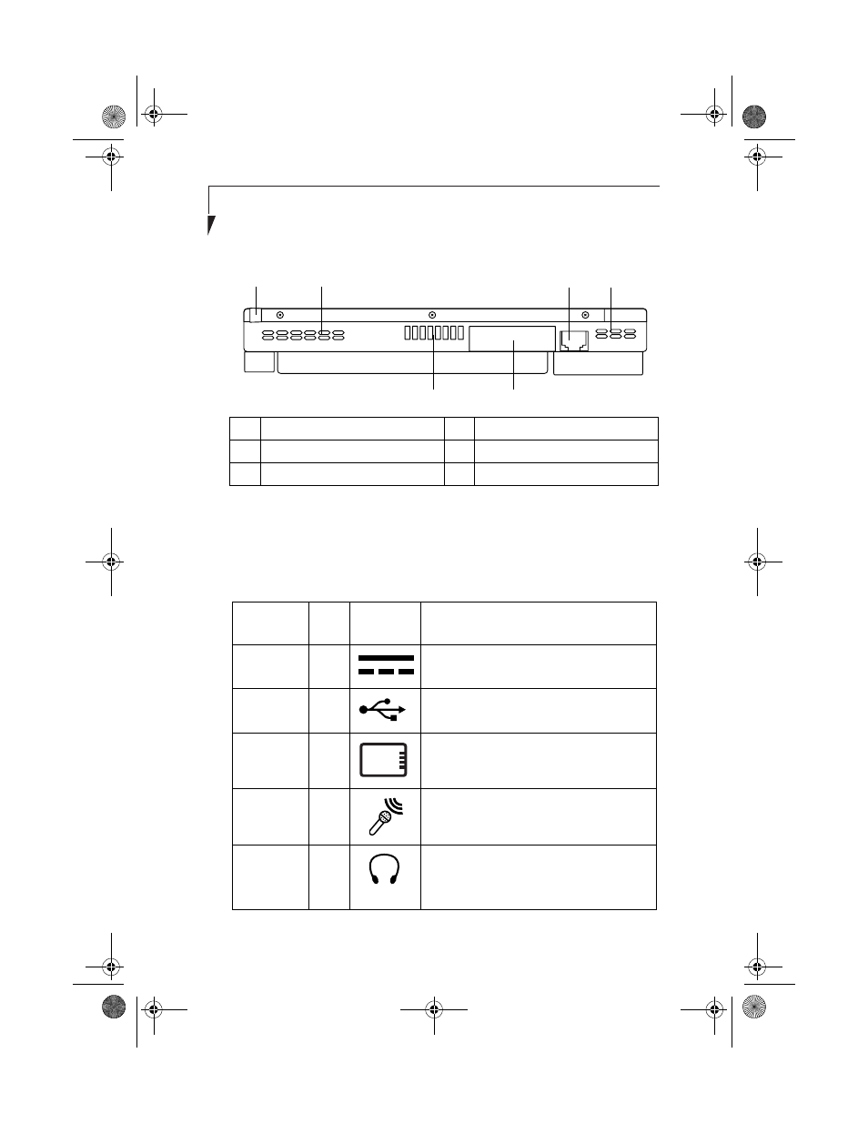
Figure 1-6 Bottom Connectors and Interfaces
Table 1-2 provides a description of each peripheral connector on the Stylistic
LT800P tablet. Each of the illustrated icons is printed on the tablet case.
1
Infrared keyboard port
4
Air flow vents
2
Air flow vents
5
Mini-dock interface cover
3
LAN port (RJ-45)
6
Charging contacts
Table 1-2. Peripheral Connectors/Interfaces
Connector/
Peripheral
Fig.
Ref.
Tablet Icon
Purpose
DC input
connector
1-4
Connect an external power source such as the
AC adapter or auto adapter.
USB Port
1-4
Connect Universal Serial Bus-compliant
devices to the tablet.
PCMCIA
CardBus slot
1-5
Install a Type I or Type II PC Card.
Microphone
jack
1-5
Connect an external microphone. The internal
microphone is disabled when you plug in an
external microphone.
Headphone
jack
1-5
Connect stereo headphones or powered
external speakers. The internal speaker is
disabled when you plug in external
headphones or speakers.
1
2
3
4
5
6
58-0867-01.book Page 20 Thursday, February 13, 2003 1:18 PM