FANUC Robotics America GFK-1535A User Manual
Page 85
6-4
VersaMax™ System Genius® Network Interface Unit User's Manual – November 2000
GFK-1535A
6
T
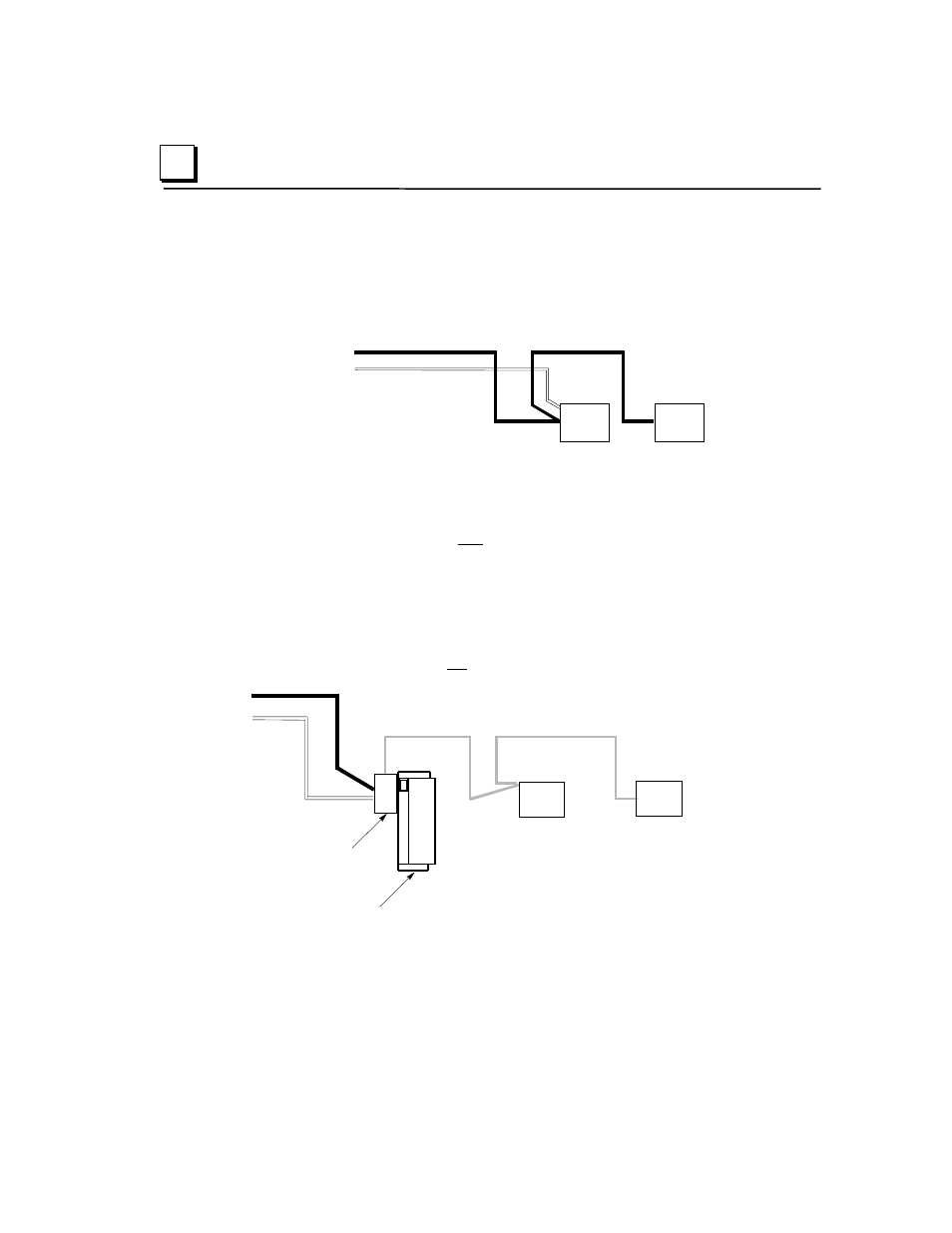
An NIU can be located on one bus of a redundant bus pair, if bus
redundancy is not needed for the modules in that station. In this example, the
NIU on the left is connected to both Bus A and Bus B and is configured as a
bus switching device. The NIU on the right, which serves non-critical I/O
modules, is connected to Bus A only, and is not configured as a bus switching
device.
Bus A
Bus B
NIU
NIU
T
An NIU can be located on a bus stub. A Network Interface Unit can also be
located on a bus stub, which is a short length of unterminated cable
downstream of another type of bus switching device, such as a Genius I/O
block/Bus Switching Module combination, or a Remote I/O Scanner connected
to a dual bus. Because the bus stub cable itself is not redundant, this type of
installation does not provide as much protection as connecting directly to a dual
bus. The bus switching device to which the bus stub is connected can be
another Genius block with a Bus Switching Module attached, as shown below,
or a Series 90-70 Remote I/O Scanner.
In this example, there are two I/O stations installed on a bus stub. Each is
configured as “BSM Present” but not configured as a “BSM Controller”
Bus A
Bus B
Bus
Switching
Module
Genius Block
Acting as a
BSM Controller
Up to 7 Additional Devices on the Bus Stub
NIU
NIU
Up to seven devices can be installed on a bus stub. Each device on a bus stub
counts toward the total of 32 devices on the Genius bus.
Restrictions on the number and length of bus stubs that may be used on a dual bus
are explained in the Genius I/O System and Communications User's Manual.