Configuring “racks” and “slots, 4configuring “racks” and “slots – FANUC Robotics America GFK-1535A User Manual
Page 51
GFK-1535A
Chapter 4 Configuring a Genius NIU and I/O Station
4-3
4
Configuring “Racks” and “Slots”
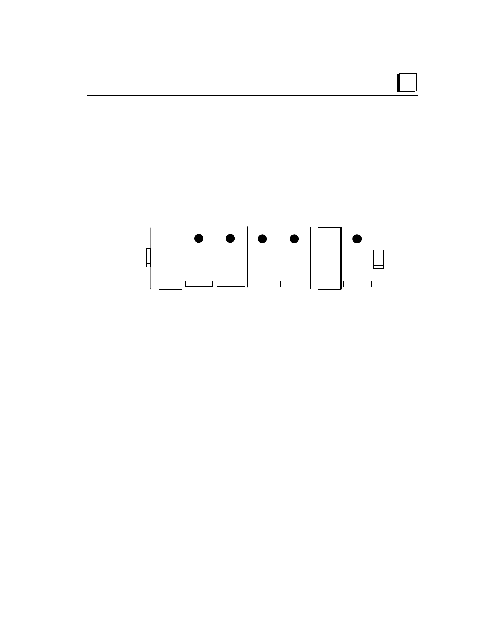
Even though a VersaMax I/O Station does not have a module rack, both
autoconfiguration and software configuration use the traditional convention of
“racks” and “slots” to identify module locations. Each logical rack consists of the
NIU or an Expansion Receiver module plus up to 8 additional I/O and option
modules mounted on the same DIN rail. Each I/O or option module occupies a
“slot”. The module next to the NIU or Expansion Receiver module is in slot 1.
Booster power supplies do not count as occupying slots.
1
Booster Power
Supply
NIU
2
3
4
5
Main Rack (rack 0)
The main rack is rack 0. Additional racks are numbered 1 to 7.