FANUC Robotics America GFK-1535A User Manual
Page 52
4-4
VersaMax™ System Genius® Network Interface Unit User's Manual – November 2000
GFK-1535A
4
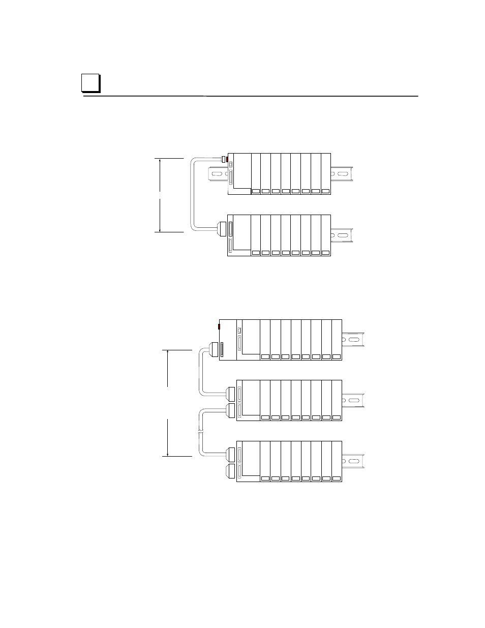
In an I/O Station that has one expansion rack attached to the expansion bus by a
non-isolated Expansion Receiver Module (IC200ERM002), the expansion rack
must be configured as rack 1.
PS
ERM
VersaMax Expansion Rack
1 M
VersaMax I/O Station Main Rack
PS
NIU
In an I/O Station with an Expansion Transmitter Module (IC200BTM001) and up to
seven expansion “racks”, each with an Expansion Receiver Module (IC200ERM001
or IC200ERM002), the additional racks are configured as rack 1 through rack 7.
PS
NIU
PS
ERM
PS
ERM
ETM
VersaMax ExpansionRack 1
Terminator
Plug
15M with any
IC200ERM002 ERMs
750M with all
IC200ERM001 ERMs
VersaMax I/O Station Main Rack (0)
VersaMax ExpansionRack 7