FUJITSU MCJ3230AP User Manual
Page 64
Installation Requirements
3-16
C156-E205-01EN
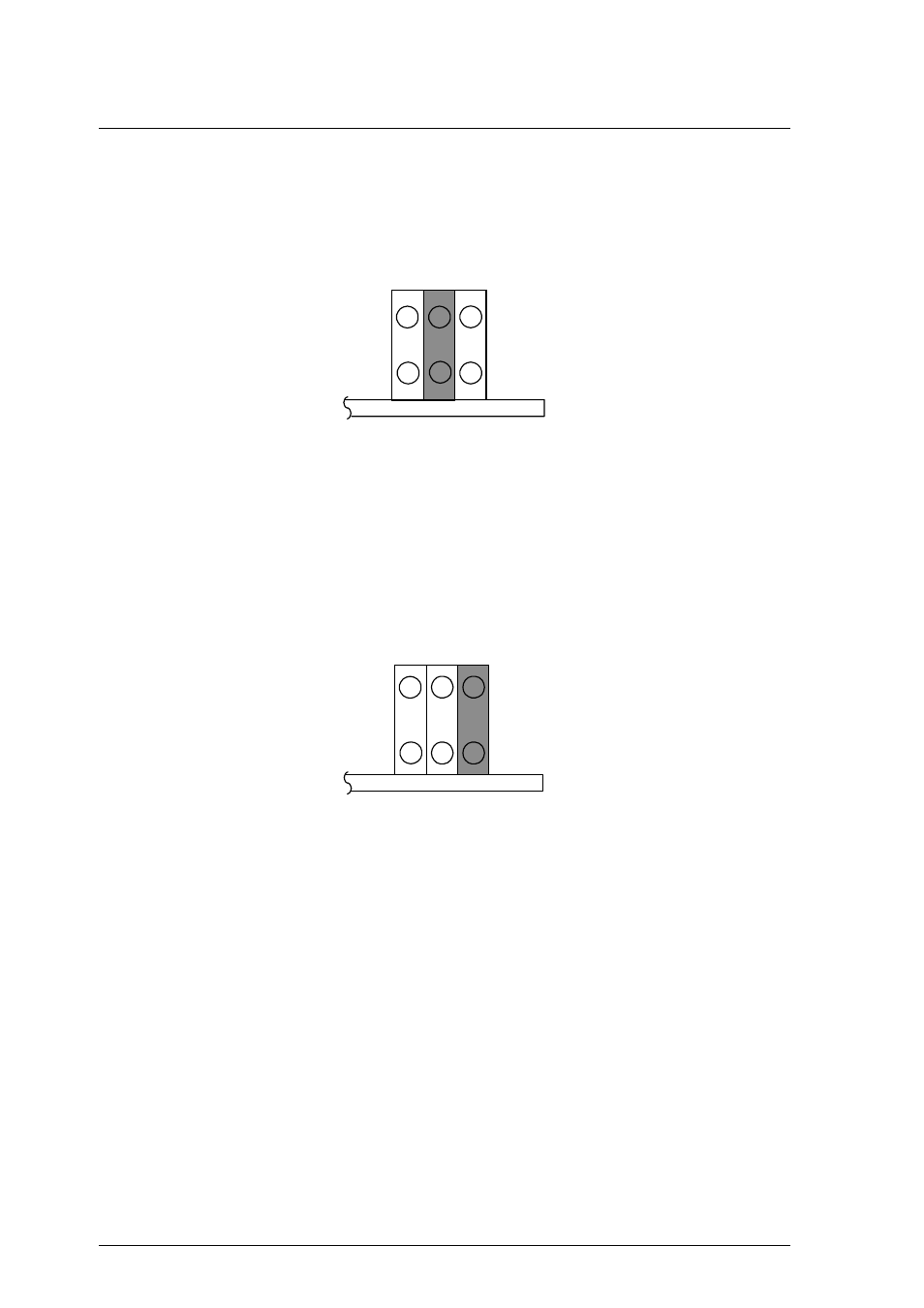
(2) Setting slave device mode
Figure 3.13 shows the setting for recognizing the slave device (device 1).
CNH5
3
1
4
2
5
6
Figure 3.13 Slave device setting
(3) Setting cable select mode
Figure 3.14 shows the master device/slave device setting when the CSEL signal is
connected to the interface. In the example shown in Figure 3.15, this setting
requires a special interface connection.
CNH5
3
1
4
2
5
6
Figure 3.14 Cable select mode setting
Figure 3.15 shows a cable select example using a special interface cable.
This example connects CSEL of the master device to the CSEL line (conductor) of
the cable, then grounds it so that the drive recognizes that it is the master. At this
time, the CSEL conductor of the slave device is removed and cannot be connected
to CSEL of the cable, so that the drive recognizes that it is the slave.
- XG Series P3NK-4452-01ENZD (614 pages)
- FPCAC14C (1 page)
- MCJ3230SS (161 pages)
- MBA3073NC (138 pages)
- T5140 (102 pages)
- T5140 (76 pages)
- MAM3367MC/MP (152 pages)
- MPC3045AH (185 pages)
- MB2142-02 (23 pages)
- MB15F86UL (6 pages)
- MHS2030AT (40 pages)
- MHW2100BS (296 pages)
- MHK2060AT (227 pages)
- Disk Drives MHK2060AT (227 pages)
- MCM3064SS (170 pages)
- Mainboard D1561 (45 pages)
- MHC2040AT (219 pages)
- D1961 (45 pages)
- DISK DRIVES MHM2100AT (231 pages)
- MHR2010AT (250 pages)
- MHZ2120BJ (320 pages)
- MCE3064AP (175 pages)
- LQFP-64P (16 pages)
- Solaris PCI GigabitEthernet 3.0 (115 pages)
- MAY2036RC (94 pages)
- MAB3091 (142 pages)
- MPE3XXXAT (191 pages)
- MHV2040AH (40 pages)
- MHW2040AC (278 pages)
- ETERNUSmgr P2X0-0202-01EN (64 pages)
- VSS Hardware Provider 2.1 (134 pages)
- MAG3182FC (61 pages)
- MAU3147NC/NP (130 pages)
- MAX3147RC (94 pages)
- MHV2160BT (296 pages)
- MHV2040AT (280 pages)
- MAW3300NC/NP (130 pages)
- DeskPower E623 (50 pages)
- MAG3182LC (133 pages)
- OPTICAL DISK DRIVES MDG3064UB (42 pages)
- MHF2021AT (225 pages)
- MHR2040AT (40 pages)
- Single Drive FTM7926FB (1 page)
- PG-FCS103 (98 pages)
- MAS3735FC (114 pages)