4 control circuit section – FUJITSU MCJ3230AP User Manual
Page 34
General Description
1-8
C156-E205-01EN
The positioner is driven by a linear voice coil motor. A pulse-width modulation
(PWM) is adopted as a driving system and realizes low power consumption and
high-speed access.
(4) Separate optical sections
The optical head section is separated in such a way that the fixed optics section
is separated from the moving optics section to minimize seek time and positioning
error. (See Subsection 1.2.4 for the fixed optical section.) This reduces the weight
of the moving parts.
The fixed optics section consists of the laser diodes, collimator lens, and optical
detector.
The fixed optics section includes a laser diode for recording and playback, and
transmits one laser beam to the head actuator.
(5) Panel
The central part of the panel is hollowed out deeply to provide pushing finger
space for inserting the cartridge, thereby facilitating the insertion.
The panel is also simply designed by making the eject button and LED light
emitting part integral with each other.
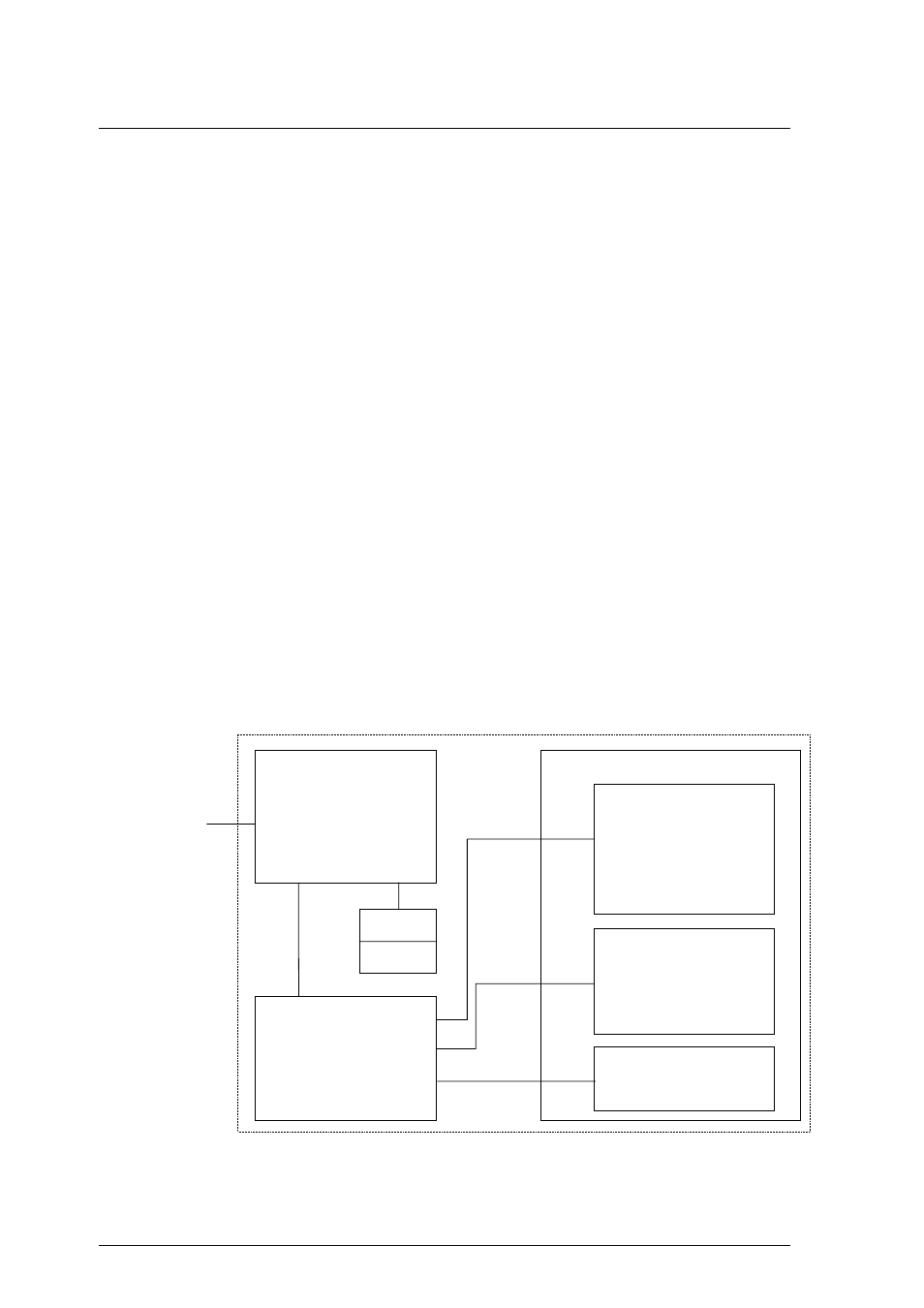
1.2.4 Control circuit section
Figure 1.4 is the block diagram of the control circuit section.
Figure 1.4 Control circuit section block diagram
DE
ATAPI I/F
Actuator
Focus Act.
Track Act.
Spindle Motor
Temperature Sensor
Head
Laser Diode
Photo Diode
APC Amp
LPC Amp
Servo AGC
Drive
Read Amp
Power Amp
Filter
Sensor
Motor Driver
Main control
MPU
ODC
DSP
User Logic
LSI i/f
D-RAM
F-ROM
Bias Coil
Eject Motor
Cartridge Sensor