Operating sequence – Bryant 579F User Manual
Page 52
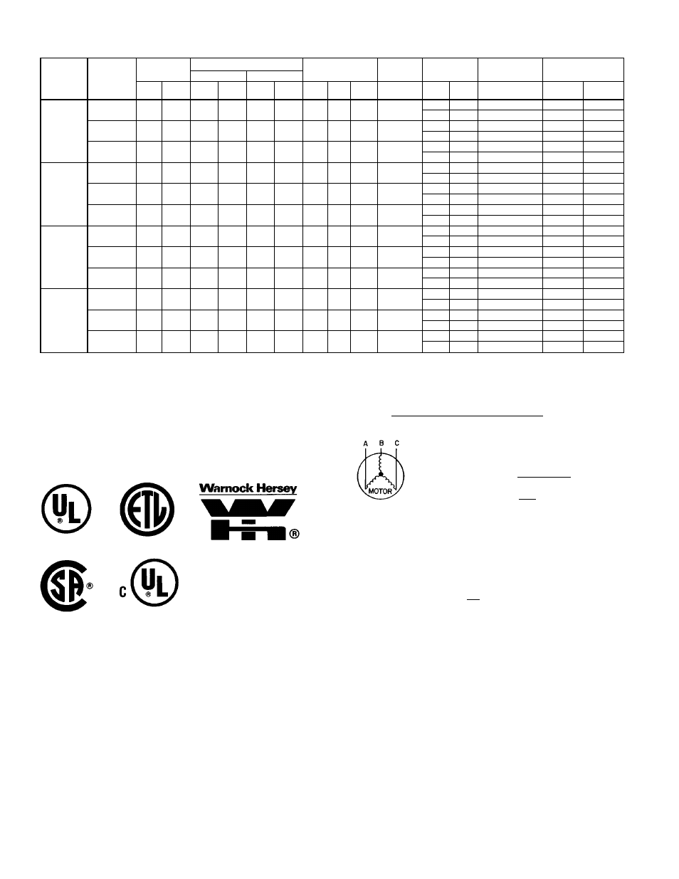
ELECTRICAL DATA — 579F180-300
UNIT
579F
NOMINAL
VOLTAGE
(60 Hz)
VOLTAGE
RANGE
COMPRESSOR
OFM
IFM
POWER
EXHAUST
COMBUSTION
FAN MOTOR**
POWER SUPPLY
NO. 1
NO. 2
Min
Max
RLA
LRA
RLA
LRA
Qty
Hp
FLA
(ea)
FLA
FLA
LRA
FLA
MCA
MOCP†
180
(15 Tons)
208/230
(3 phase)
187
254
61.0
266
—
—
3
1
⁄
2
1.70
10.5/10.5
—
—
0.57
92/92
150/150
4.6
18.8
0.57
96/96
150/150
460
(3 phase)
414
508
28.0
120
—
—
3
1
⁄
2
0.08
4.8
—
—
0.30
42
70
2.3
6.0
0.30
45
70
575
(3 phase)
518
632
23.0
96
—
—
3
1
⁄
2
0.75
3.9
—
—
0.57
35
50
2.1
4.8
0.57
37
60
216
(18 Tons)
208/230
(3 phase)
187
254
28.3
205
25.0
185
3
1
⁄
2
1.70
15.8/15.8
—
—
0.57
81/81
100/100
4.6
18.8
0.57
86/86
110/110
460
(3 phase)
414
508
14.4
104
12.4
89
3
1
⁄
2
0.80
7.9
—
—
0.30
41
50
2.3
6.0
0.30
43
50
575
(3 phase)
518
632
11.4
78
10.4
78
3
1
⁄
2
0.75
6.0
—
—
0.57
33
40
2.1
4.8
0.57
35
45
240
(20 Tons)
208/230
(3 phase)
187
254
34.5
239
28.3
205
2
1
5.50
25.0/25.0
—
—
0.57
107/107
125/125
4.6
18.8
0.57
112/112
125/125
460
(3 phase)
414
508
17.0
119
14.4
104
2
1
2.80
13.0
—
—
0.30
54
70
2.3
6.0
0.30
57
70
575
(3 phase)
518
632
15.2
111
11.4
78
2
1
3.40
10.0
—
—
0.57
47
60
2.1
4.8
0.57
49
60
300
(25 Tons)
208/230
(3 phase)
187
254
43.6
228
43.6
228
2
1
5.50
28.0/28.0
—
—
0.57
137/137
175/175
4.6
18.8
0.57
142/142
175/175
460
(3 phase)
414
508
22.1
114
22.1
114
2
1
2.80
14.6
—
—
0.30
70
90
2.3
6.0
0.30
72
90
575
(3 phase)
518
632
17.9
91
17.9
91
2
1
3.40
13.0
—
—
0.57
60
70
2.1
4.8
0.57
62
80
LEGEND
CSA
— Canadian Standards Association
CUL
— Underwriters’ Laboratory Canada
FLA
— Full Load Amps
HACR
— Heating, Air Conditioning and Refrigeration
IFM
— Indoor (Evaporator) Fan Motor
LRA
— Locked Rotor Amps
MCA
— Minimum Circuit Amps
MOCP — Maximum Overcurrent Protection
NEC
— National Electrical Code
OFM
— Outdoor (Condenser) Fan Motor
RLA
— Rated Load Amps
*Used to determine minimum disconnect size per NEC.
†Fuse or HACR circuit breaker.
**The 579F240 and 300 high-heat units have 2 combustion-fan motors.
036-150 Only
180-300 Only
180-300 Only
036-072 Only
090-150 Only
NOTES:
1. In compliance with NEC requirements for multimotor and combination load
equipment (refer to NEC Articles 430 and 440), the overcurrent protective de-
vice for the unit shall be fuse or HACR breaker. Canadian units may be fuse or
circuit breaker.
2. Unbalanced 3-Phase Supply Voltage
Never operate a motor where a phase imbalance in supply voltage is greater
than 2%.
Use the following formula to determine the percent voltage imbal-
ance.
% Voltage Imbalance
max voltage deviation from average voltage
= 100 x
average voltage
EXAMPLE: Supply voltage is 460-3-60.
AB =452 v
BC =464 v
AC =455 v
452 +464 +455
Average Voltage =
3
1371
=
3
= 457
NOTE: The 575-v 580D036-150 units are CSA or CUL only.
Determine maximum deviation from average voltage.
(AB) 457 - 452 = 5 v
(BC) 464 - 457 = 7 v
(AC) 457 - 455 = 2 v
Maximum deviation is 7 v.
Determine percent voltage imbalance.
7
% Voltage Imbalance = 100 x
457
= 1.53%
This amount of phase imbalance is satisfactory as it is below the maximum al-
lowable 2%.
IMPORTANT: If the supply voltage phase imbalance is more than 2%, contact
your local electric utility company immediately.
OPERATING SEQUENCE
COOLING, UNITS WITHOUT ECONOMIZER — When thermostat
calls for cooling, terminals G and Y1 are energized. The indoor
(evaporator) fan contactor (IFC) and compressor contactor no. 1
(C1) are energized, and evaporator-fan motor, compressor no. 1
(580D036-150
and
579F216-300)
or
unloaded
compressor
(579F180), and condenser fan(s) start. The condenser-fan motor(s)
runs continuously while unit is cooling. For units with 2 stages of
cooling, if the thermostat calls for a second stage of cooling by en-
ergizing Y2, compressor contactor no. 2 (C2) is energized and com-
pressor
no.
2
starts
(580D090-150
and
579F216-300)
or
compressor no. 1 runs fully loaded (579F180).
HEATING, UNITS WITHOUT ECONOMIZER (580D036-150) —
When the thermostat calls for heating, terminal W1 is energized. In
order to prevent thermostat short-cycling, the unit is locked into the
Heating mode for at least 1 minute when W1 is energized. The
induced-draft motor (IDM) is then energized and the burner ignition
sequence begins. The indoor (evaporator) fan motor (IFM) is ener-
gized 45 seconds after a flame is ignited. On units equipped for two
stages of heat, when additional heat is needed, W2 is energized
and the high-fire solenoid on the main gas valve (MGV) is ener-
gized. When the thermostat is satisfied and W1 is deenergized, the
IFM stops after a 45-second time-off delay.
HEATING, UNITS WITHOUT ECONOMIZER (579F180-300)
NOTE: The 579F180-300 units have 2 stages of heat.
Set thermostat system switch at HEAT or AUTO. position and set
fan switch to AUTO. position for heating.
52