Bryant 579F User Manual
Page 16
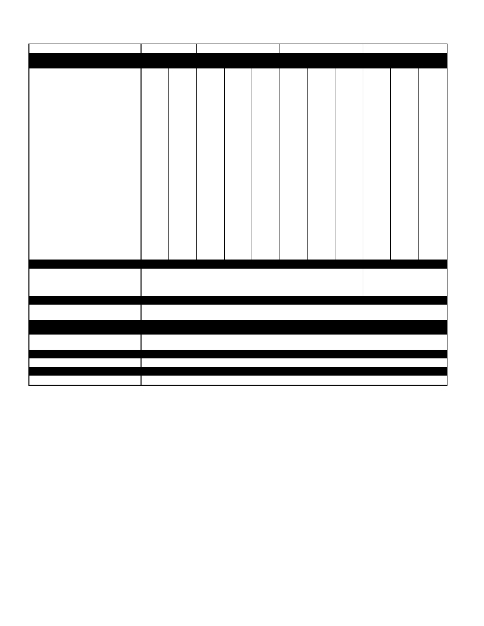
SPECIFICATIONS — 580D036-072 (cont)
UNIT SIZE
036
048
060
072
FURNACE SECTION
Medium
Heat
High
Heat
Low
Heat
Medium
Heat
High
Heat
Low
Heat
Medium
Heat
High
Heat
Low
Heat
Medium
Heat
High
Heat
Rollout Switch Cutout
Temp (F)†
195
195
195
195
195
195
195
195
195
195
195
Burner Orifice Diameter
(in. ...drill size)
Natural Gas
Std .113...33 .113...33 .113...33 .113...33 .129...30 .113...33 .113...33 .129...30 .113...33 .113...33 .129...30
Liquid Propane
Alt .089...43 .089...43 .089...43 .089...43 .102...38 .089...43 .089...43 .102...38 .089...43 .089...43 .102...38
Pilot Orifice Diameter
(in. ...drill size)
Natural Gas
Std
—
—
—
—
—
—
—
—
—
—
—
Liquid Propane
Alt
—
—
—
—
—
—
—
—
—
—
—
Thermostat Heat Anticipator
Setting (amps)
208/230, 575 v Stage 1
.14
.14
.14
.14
.14
.14
.14
.14
.14
.14
.14
Stage 2
—
.14
—
—
.14
—
—
.14
—
—
.14
460 v Stage 1
.14
.14
.14
.14
.14
.14
.14
.14
.14
.14
.14
Stage 2
—
.14
—
—
.14
—
—
.14
—
—
.14
Gas Input (Btuh) Stage 1
72,000
82,000
72,000
115,000 120,000
72,000
115,000 120,000
72,000
115,000 120,000
Stage 2
—
115,000
—
—
150,000
—
—
150,000
—
—
150,000
Efficiency (Steady State) (%)
80
80
80
80
80
80
80
80
80
80
80
Temperature Rise Range
25-55
55-85
25-55
35-65
50-80
25-55
35-65
50-80
25-55
35-65
50-80
Manifold Pressure (in. wg)
Natural Gas
Std
3.5
3.5
3.5
3.5
3.5
3.5
3.5
3.5
3.5
3.5
3.5
Liquid Propane
Alt
3.5
3.5
3.5
3.5
3.5
3.5
3.5
3.5
3.5
3.5
3.5
Gas Valve Quantity
1
1
1
1
1
1
1
1
1
1
1
Gas Valve Pressure Range
Psig
0.180-
0.487
0.180-
0.487
0.180-
0.487
0.180-
0.487
0.180-
0.487
0.180-
0.487
0.180-
0.487
0.180-
0.487
0.180-
0.487
0.180-
0.487
0.180-
0.487
in. wg
5.0-13.5 5.0-13.5 5.0-13.5 5.0-13.5 5.0-13.5 5.0-13.5 5.0-13.5 5.0-13.5 5.0-13.5 5.0-13.5 5.0-13.5
Field Gas Connection
Size (in.)
1
⁄
2
1
⁄
2
1
⁄
2
1
⁄
2
1
⁄
2
1
⁄
2
1
⁄
2
1
⁄
2
1
⁄
2
1
⁄
2
1
⁄
2
HIGH-PRESSURE SWITCH (psig)**
Standard Compressor
Internal Relief
450 ± 50
500 ± 50
Cutout
428
428
Reset (Auto.)
320
320
LOW-PRESSURE SWITCH (psig)**
Cutout
7 ± 3
Reset (Auto.)
22 ± 7
FREEZE PROTECTION
THERMOSTAT (F)**
Opens
30 ± 5
Closes
45 ± 5
OUTDOOR-AIR INLET SCREENS
Cleanable
Quantity...Size (in.)
1...20 x 24 x 1
RETURN-AIR FILTERS
Throwaway
Quantity...Size (in.)
2...16 x 25 x 2
LEGEND
Al
— Aluminum
Bhp
— Brake Horsepower
FIOP — Factory-Installed Option
*Evaporator coil fin material/condenser coil fin material.
†Rollout switch is manual reset.
**Requires the accessory controls upgrade kit.
††Weight of 14-in. roof curb.
Low-heat weight/high-heat weight.
¶Circuit 1 consists of lower portion of condenser coil and lower portion of evaporator coil, and Circuit 2 is the upper
portion of both coils.
***The 579F300 unit requires 2-in. industrial-grade filters capable of handling face velocities of up to 625 ft/min.
NOTE: The 580D036-150 units have a loss-of-charge/low-pressure switch (accessory) located in the liquid line. The
579F180-300 units have a low-pressure switch (standard) located on the suction side.
16