Bryant 579F User Manual
Page 17
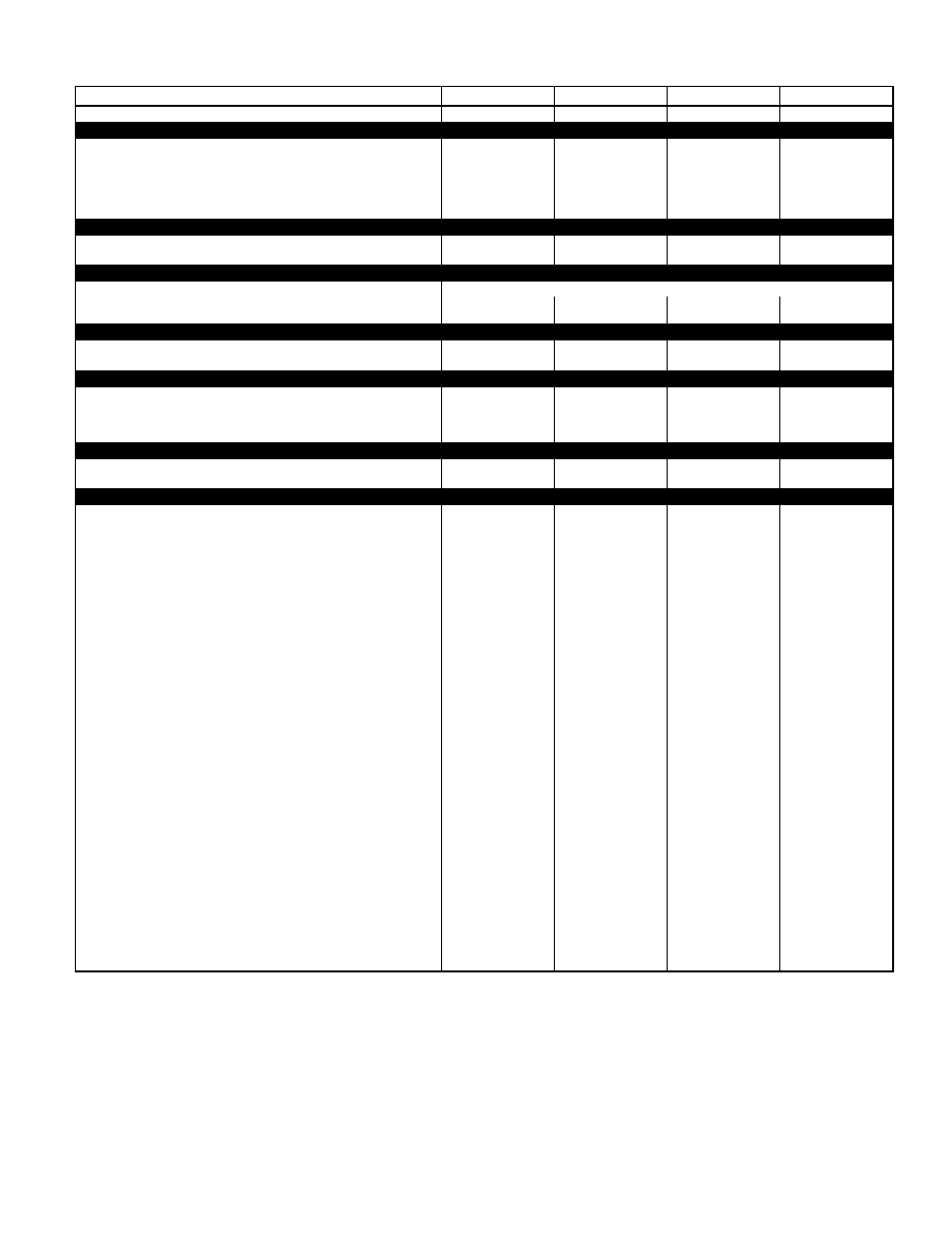
SPECIFICATIONS — 580D090-150
UNIT SIZE
090
102
120
150
NOMINAL CAPACITY (tons)
7
1
⁄
2
8
1
⁄
2
10
12
1
⁄
2
OPERATING WEIGHT (lb)
Unit
Al/Al*
870
880
1035
1050
Economizer
Varislide™
44
44
44
44
Parablade
62
62
62
62
Roof Curb††
143
143
143
143
COMPRESSOR
Hermetic
Quantity
2
2
2
2
Oil (oz)
50 ea
50 ea
50 ea
54 ea
REFRIGERANT TYPE
R-22
Operating Charge (lb-oz)
Circuit 1
4-13
6-14
5-13
9-6
Circuit 2
4-14
6-3
5-14
9-0
CONDENSER COIL
Enhanced Copper Tubes, Aluminum Lanced Fins
Rows...Fins/in.
1...17
2...17
2...17
2...17
Total Face Area (sq ft)
20.50
18.00
17.42
25.00
CONDENSER FAN
Propeller Type
Nominal Cfm
6500
6500
7000
7000
Quantity...Diameter (in.)
2...22
2...22
2...22
2...22
Motor Hp...Rpm
1
⁄
4
...1100
1
⁄
4
...1100
1
⁄
4
...1100
1
⁄
4
...1100
Watts Input (Total)
600
600
600
600
EVAPORATOR COIL
Enhanced Copper Tubes, Aluminum Double-Wavy Fins
Rows...Fins/in.
3...15
3...15
3...15
4...15
Total Face Area (sq ft)
8.0
8.0
10.0
11.1
EVAPORATOR FAN
Centrifugal Type
Quantity...Size (in.)
Std
1...15 x 15
1...15 x 15
1...15 x 15
1...15 x 15
Alt
1...15 x 15
—
1...15 x 15
1...15 x 15
Type Drive
Std
Belt
Belt
Belt
Belt
Alt
Belt
—
Belt
Belt
Nominal Cfm
3000
3400
4000
5000
Motor Hp
Std
—
—
—
—
Alt
—
—
—
—
Maximum Continuous Bhp
Std
2.40
2.40
2.40
4.20
Alt
—
—
2.90
5.25
Motor Frame Size
Std
56
56
56
56
Alt
—
—
56
56
Nominal Rpm High/Low
Std
—
—
—
—
Alt
—
—
—
—
Fan Rpm Range
Std
590-840
685-935
685-935
860-1080
Alt
685-935
—
835-1085
900-1260
Motor Bearing Type
Ball
Ball
Ball
Ball
Maximum Allowable Rpm
2100
2100
2100
2100
Motor Pulley Pitch Diameter Min/Max (in.)
Std
2.4/3.4
2.8/3.8
2.8/3.8
4.0/5.0
Alt
2.8/3.8
—
3.4/4.4
3.1/4.1
Nominal Motor Shaft Diameter (in.)
Std
5
⁄
8
5
⁄
8
5
⁄
8
7
⁄
8
Alt
—
—
7
⁄
8
7
⁄
8
Fan Pulley Pitch Diameter (in.)
Std
7.0
7.0
7.0
8.0
Alt
7.0
—
7.0
5.9
Nominal Fan Shaft Diameter (in.)
—
—
—
—
Belt, Quantity...Type...Length (in.)
Std
1...A...48
1...A...48
1...A...51
1...A...51
Alt
1...A...51
—
1...A...57
1...BX...46
Pulley Center Line Distance (in.)
Std
16.75-19.25
16.75-19.25
15.85-17.50
15.85-17.50
Alt
16.75-19.25
—
15.85-17.50
15.85-17.50
Speed Change per Full Turn of
Std
50
50
50
44
Movable Pulley Flange (rpm)
Alt
50
—
50
50
Movable Pulley Maximum Full Turns
Std
5
5
5
5
From Closed Position
Alt
5
—
5
6
Factory Setting
Std
5
5
5
5
Alt
5
—
5
6
Factory Speed Setting (rpm)
Std
590
685
685
860
Alt
685
—
835
960
Fan Shaft Diameter at Pulley (in.)
1
1
1
1
(Table continued on next page.)
LEGEND
Al
— Aluminum
Bhp
— Brake Horsepower
FIOP — Factory-Installed Option
*Evaporator coil fin material/condenser coil fin material.
†Rollout switch is manual reset.
**Requires the accessory controls upgrade kit.
††Weight of 14-in. roof curb.
Low-heat weight/high-heat weight.
¶Circuit 1 consists of lower portion of condenser coil and lower portion of evaporator coil, and Circuit 2 is the upper
portion of both coils.
***The 579F300 unit requires 2-in. industrial-grade filters capable of handling face velocities of up to 625 ft/min.
NOTE: The 580D036-150 units have a loss-of-charge/low-pressure switch (accessory) located in the liquid line. The
579F180-300 units have a low-pressure switch (standard) located on the suction side.
17