Ab c – Brother HL-1040 User Manual
Page 60
III-11
(3)
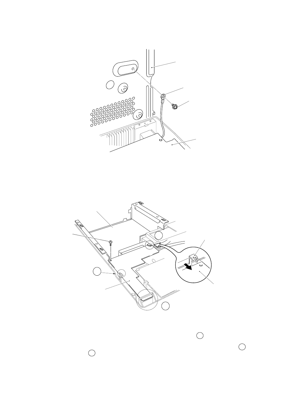
Lift the base plate ASSY and remove the grounding screw.
Fig. 3-17
3.10
Panel Sensor PCB ASSY
(1)
Remove the main shield.
(2)
Remove the M4x12 screw securing the panel sensor PCB ASSY.
Fig. 3-18
Note:
When re-assembling the main shield, ensure that you fit PCB A to underneath the
main shield.
When re-assembling the panel sensor PCB, ensure that you fit the PCB into hook B
and hook C first. Then, fit the two bosses to the PCB and secure the screw.
Base Plate ASSY
Taptite, bind M4x12
Ground wire
Panel Sensor PCB ASSY
Screw pan(washer),
M3.5x6
Main shield
Low-voltage Power
Supply PCB ASSY
Panel Sensor PCB ASSY
A
B
C
Main shield