Chapter ii theory of operation, Electronics – Brother HL-1040 User Manual
Page 17
II-1
CHAPTER II THEORY OF OPERATION
1. ELECTRONICS
1.1
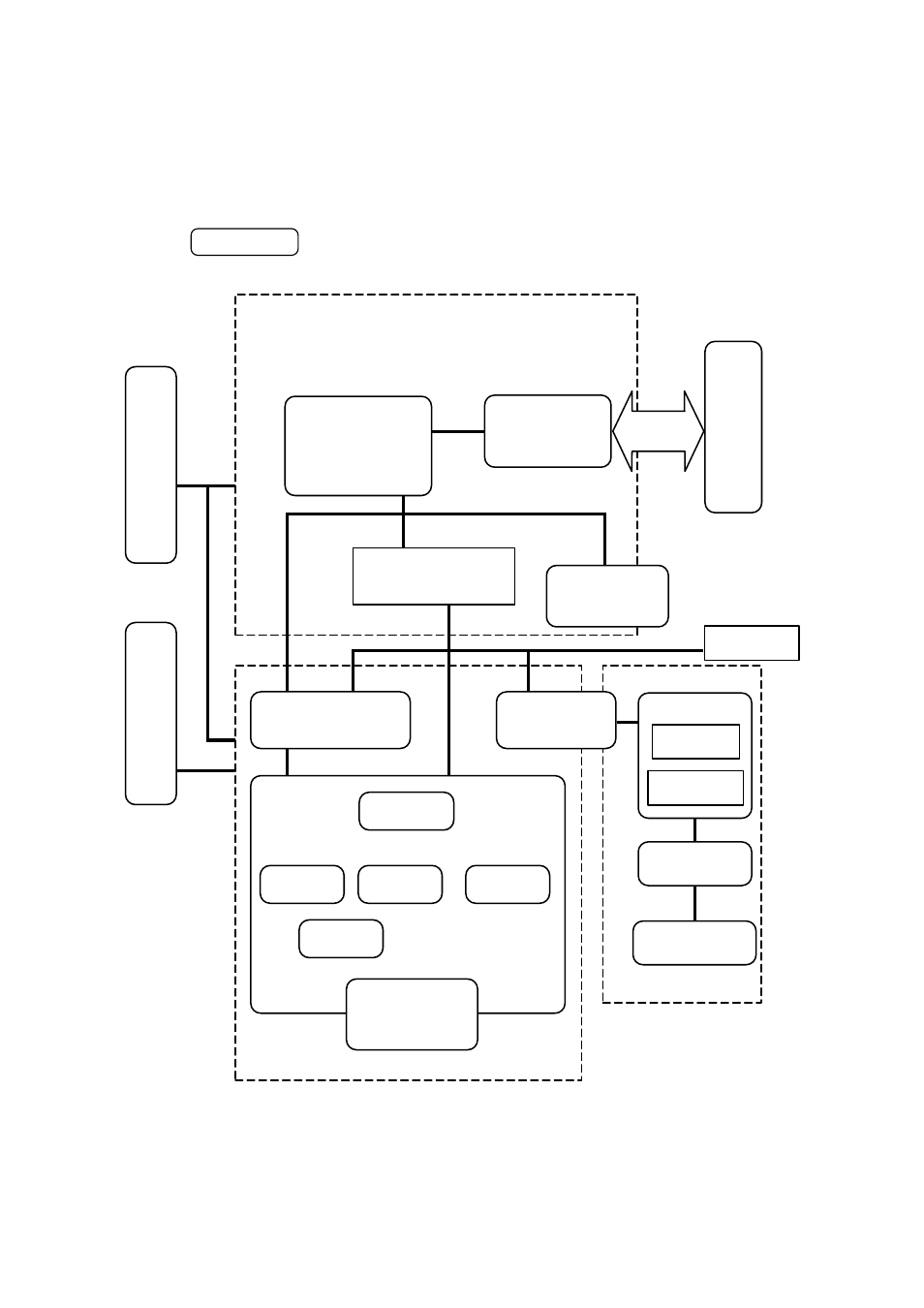
General Block Diagram
Fig. 2-1 shows a general block diagram of the HL-820/1020 printer.
Video control block
Interface block
Engine control block
Operation block
(Operation panel)
Control system
Low-voltage power
supply block
High-voltage power
supply block
Laser scanner unit
Drive block
(Stepping motor)
Drum unit
Transfer block
Developing
block
Drum
Charging
block
Cleaner
block
External device
Paper tray unit
Paper tray
Manual feed
Fixing unit
Paper eject block
Paper feed system
Image generation system
Toner cartridge
Erase lamp
Fig. 2-1
HL-820/1020