Brother HL-1040 User Manual
Page 35
II-19
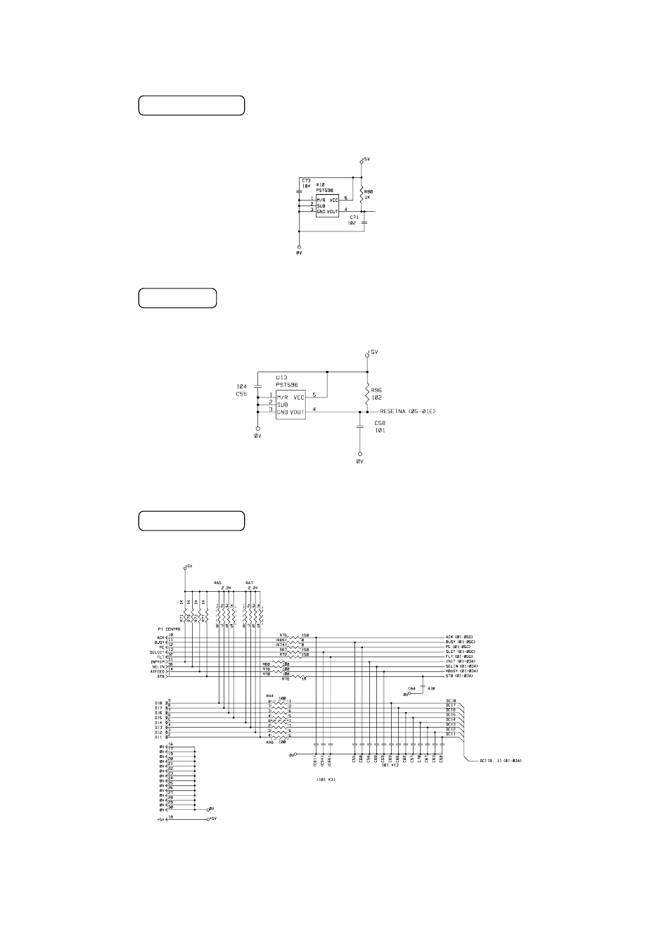
1.3.8
Reset Circuit
The reset IC is a PST598DNR. The reset voltage is 4.2V (typ.) and the LOW period of
reset is 200ms (typ).
Fig. 2-19
The reset IC is a PST596DNR. The reset voltage is 4.2V (typ.) and the LOW period of
reset is 50ms (typ).
Fig. 2-20
1.3.9
CDCC I/O
Fig. 2-21 shows the CDCC interface circuit.
Fig. 2-21
HL-1050
HL-820/1020/1040
HL-820/1020/1040
See also other documents in the category Brother Printers:
- HL-2240 (522 pages)
- HL-2240 (21 pages)
- HL-2240 (150 pages)
- HL-2240 (2 pages)
- HL 5370DW (172 pages)
- HL-2170W (138 pages)
- HL 5370DW (203 pages)
- HL 2270DW (35 pages)
- HL 2270DW (47 pages)
- HL 5370DW (55 pages)
- HL-2170W (137 pages)
- HL-2170W (52 pages)
- PT-1290 (1 page)
- DCP-385C (122 pages)
- MFC 6890CDW (256 pages)
- DCP-585CW (132 pages)
- DCP-385C (2 pages)
- DCP-383C (7 pages)
- Pocket Jet6 PJ-622 (32 pages)
- Pocket Jet6 PJ-622 (11 pages)
- Pocket Jet6 PJ-622 (48 pages)
- Pocket Jet6Plus PJ-623 (76 pages)
- PT-2700 (34 pages)
- PT-2700 (62 pages)
- PT-2700 (90 pages)
- PT-2700 (180 pages)
- PT-2100 (58 pages)
- HL 5450DN (2 pages)
- DCP-8110DN (22 pages)
- HL 5450DN (168 pages)
- HL 5450DN (2 pages)
- HL 5470DW (177 pages)
- HL 5450DN (120 pages)
- DCP-8110DN (13 pages)
- HL 5470DW (34 pages)
- HL-S7000DN (9 pages)
- HL 5470DW (30 pages)
- MFC-J835DW (13 pages)
- DCP-8110DN (36 pages)
- HL-6050D (37 pages)
- HL-7050N (17 pages)
- HL-6050DN (138 pages)
- HL-6050D (179 pages)
- PT-1280 (1 page)
- PT-9800PCN (32 pages)