Is olat e d digital i /o module – Intelligent Motion Systems Modular LYNX System User Manual
Page 50
1 - 50
Modular LYNX System 12.05.2003
I n p u t F i l t e r i n g
User definable Digital filtering makes the LYNX
well suited for noisy industrial environments. The
filter setting is software selectable using the
IOF
Variable
with a minimum guaranteed detectable
pulse width of 18 microseconds to 2.3 millisec-
onds.
The table at right illustrates the IOF settings.
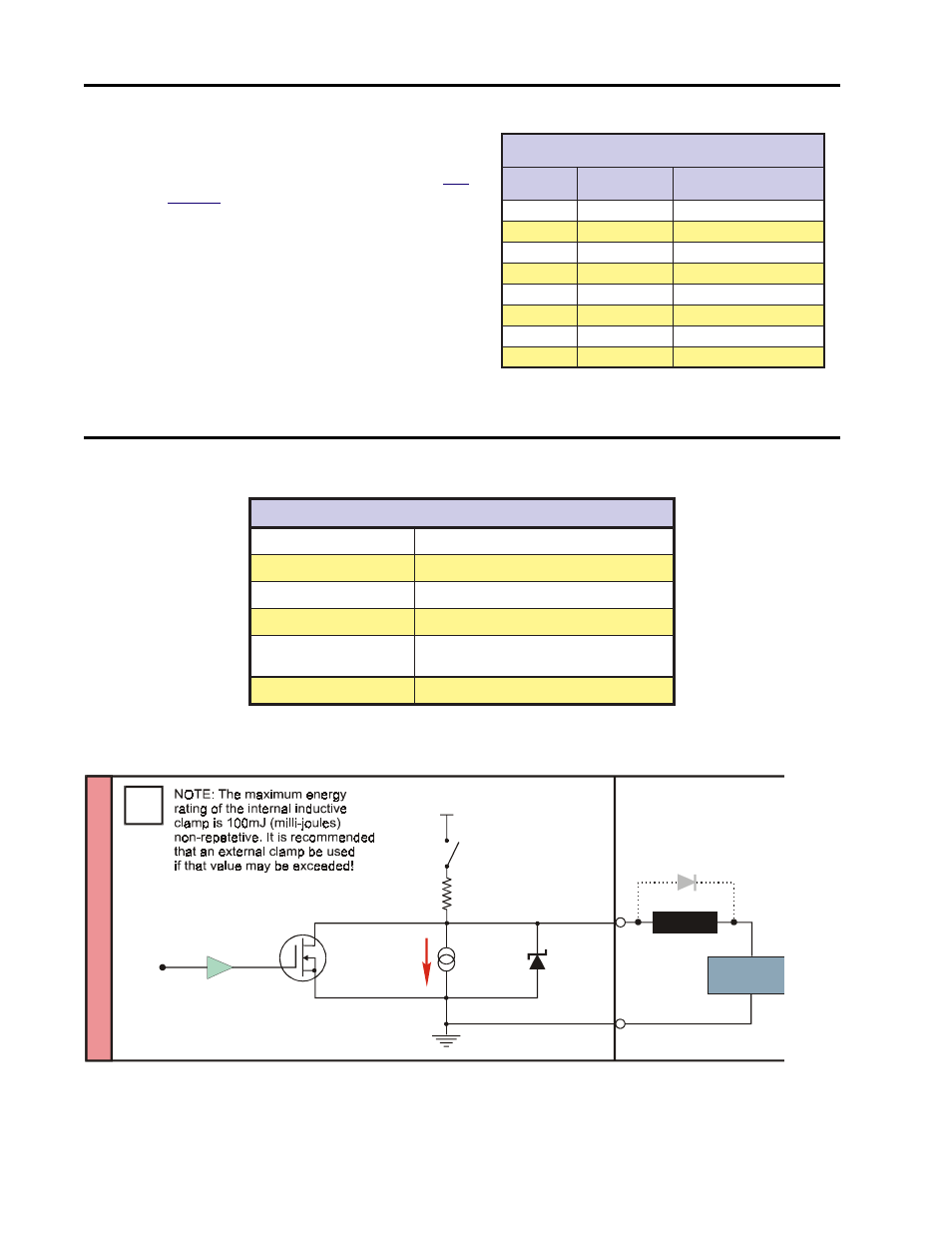
O u t p u t S p e c i f i c a t i o n s
Figure 9.4: LYNX Isolated I/O Output Equivalent Circuit
Table 9.6: Digital Filter Settings for the Isolated I/O
O
/
I
d
e
t
a
l
o
s
I
e
s
o
p
r
u
P
l
a
r
e
n
e
G
e
h
t
r
o
f
s
g
n
i
t
t
e
S
r
e
t
l
i
F
F
O
I
)
7
-
0
=
>
m
u
n
<
(
>
m
u
n
<
=
F
O
I
g
n
i
t
t
e
S
r
e
t
l
i
F
f
f
o
t
u
C
y
c
n
e
u
q
e
r
F
e
s
l
u
P
e
l
b
a
t
c
e
t
e
D
m
u
m
i
n
i
M
h
t
d
i
W
0
z
H
k
5
.
7
2
s
d
n
o
c
e
s
o
r
c
i
m
8
1
1
z
H
k
7
.
3
1
s
d
n
o
c
e
s
o
r
c
i
m
6
3
2
z
H
k
9
8
.
6
s
d
n
o
c
e
s
o
r
c
i
m
3
7
3
z
H
k
4
4
.
3
s
d
n
o
c
e
s
o
r
c
i
m
5
4
1
4
z
H
k
2
7
.
1
s
d
n
o
c
e
s
o
r
c
i
m
0
9
2
5
z
H
0
6
8
s
d
n
o
c
e
s
o
r
c
i
m
1
8
5
6
z
H
0
3
4
s
d
n
o
c
e
s
il
l
i
m
2
6
1
.
1
)
t
l
u
a
f
e
d
(
7
z
H
5
1
2
s
d
n
o
c
e
s
il
l
i
m
3
2
3
.
2
Table 9.5: Digital Filter Settings for the Isolated I/O
s
n
o
i
t
a
c
i
f
i
c
e
p
S
t
u
p
n
I
O
/
I
d
e
t
a
l
o
s
I
e
g
a
tl
o
V
y
l
p
p
u
S
d
a
o
L
m
u
m
i
x
a
M
C
D
V
8
2
e
c
n
a
t
s
i
s
e
R
n
O
T
E
F
2
Ω
)
C
°
5
2
1
=
j
T
(
m
u
m
i
x
a
M
t
n
e
r
r
u
C
k
n
i
S
s
u
o
u
n
i
t
n
o
C
)
C
°
5
2
=
a
T
(
t
u
p
t
u
O
h
c
a
E
m
u
m
i
x
a
M
A
m
0
5
3
k
n
i
S
p
u
o
r
G
m
u
m
i
x
a
M
)
d
e
t
i
m
i
L
y
ll
a
m
r
e
h
T
(
A
5
.
1
e
g
a
tl
o
V
t
u
p
t
u
O
t
i
u
c
r
i
C
n
e
p
O
V
5
.
4
=
N
O
h
c
t
i
w
S
p
u
-
ll
u
P
V
0
=
F
F
O
h
c
t
i
w
S
p
u
-
ll
u
P
Isolated Ground
Isolated
Ground
Output
Load Supply
28VDC Max
Clamp Diode
(See Note)
+5VDC
Is
olat
e
d
Digital
I
/O Module
7.5k
Ω
20 to
80 A
µ
Pull-Up
Switch
PULL-UP SWITCH =
LOAD
60V
N