Modular l ynx system, 12 3 pt hi ug – Intelligent Motion Systems Modular LYNX System User Manual
Page 19
1 - 19
Modular L
YNX System
Modular LYNX System 12.05.2003
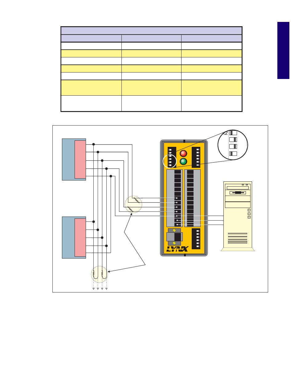
Figure 5.2: RS-232 Interface, Multiple Control Module System
Table 5.3: Connections and Settings Multiple Control Module System, RS-232 Interface
s
e
d
o
N
X
N
Y
L
e
l
p
i
t
l
u
M
r
o
f
s
n
o
i
t
c
e
n
n
o
C
d
n
A
g
n
i
r
i
W
:
e
c
a
f
r
e
t
n
I
2
3
2
-
S
R
e
l
u
d
o
M
l
o
r
t
n
o
C
t
s
o
H
1
#
e
l
u
d
o
M
l
o
r
t
n
o
C
#
e
l
u
d
o
M
l
o
r
t
n
o
C
n
7
n
i
P
)
-
X
R
(
a
t
a
D
e
v
i
e
c
e
R
9
n
i
P
)
-
X
T
(
a
t
a
D
t
i
m
s
n
a
r
T
9
n
i
P
)
-
X
T
(
a
t
a
D
t
i
m
s
n
a
r
T
8
n
i
P
)
+
X
R
(
a
t
a
D
e
v
i
e
c
e
R
0
1
n
i
P
)
+
X
T
(
a
t
a
D
t
i
m
s
n
a
r
T
0
1
n
i
P
)
+
X
T
(
a
t
a
D
t
i
m
s
n
a
r
T
9
n
i
P
)
-
X
T
(
a
t
a
D
t
i
m
s
n
a
r
T
7
n
i
P
)
-
X
R
(
a
t
a
D
e
v
i
e
c
e
R
7
n
i
P
)
-
X
R
(
a
t
a
D
e
v
i
e
c
e
R
0
1
n
i
P
)
+
X
T
(
a
t
a
D
t
i
m
s
n
a
r
T
8
n
i
P
)
+
X
R
(
a
t
a
D
e
v
i
e
c
e
R
8
n
i
P
)
+
X
R
(
a
t
a
D
e
v
i
e
c
e
R
1
1
n
i
P
d
n
u
o
r
G
s
n
o
i
t
a
c
i
n
u
m
m
o
C
1
1
n
i
P
d
n
u
o
r
G
s
n
o
i
t
a
c
i
n
u
m
m
o
C
1
1
n
i
P
d
n
u
o
r
G
s
n
o
i
t
a
c
i
n
u
m
m
o
C
N
O
=
h
c
t
i
w
S
T
S
O
H
r
o
)
1
(
E
U
R
T
=
g
a
l
F
T
S
O
H
F
F
O
=
h
c
t
i
w
S
T
S
O
H
r
o
)
0
(
E
S
L
A
F
=
g
a
l
F
T
S
O
H
F
F
O
=
h
c
t
i
w
S
T
S
O
H
r
o
)
0
(
E
S
L
A
F
=
g
a
l
F
T
S
O
H
N
O
=
h
c
t
i
w
S
Y
T
R
A
P
r
o
)
1
(
E
U
R
T
=
g
a
l
F
Y
T
R
A
P
N
O
=
h
c
t
i
w
S
Y
T
R
A
P
r
o
)
1
(
E
U
R
T
=
g
a
l
F
Y
T
R
A
P
N
O
=
h
c
t
i
w
S
Y
T
R
A
P
r
o
)
1
(
E
U
R
T
=
g
a
l
F
Y
T
R
A
P
DIR+
DIR-
SCK-
SCK+
GND
+5V
RX-
RX+
TX-
TX+
CGND
RX
TX
22
21
23
24
25
26
31
32
33
34
35
36
IG
INTELLIGENT MOTION SYSTEMS, INC.
FAULT
POWER
12
3
4
5
6
22
21
23
24
25
26
12
3
4
5
6
31
32
33
34
35
36
12
3
4
5
6
A1
A0
A2
PT
HI
UG
GND
V+
TM
CGND
RX
TX
Host PC
RX+
TX-
TX+
RX-
CGND
Control Module #2
Control Module #1
RX+
TX-
TX+
RX-
CGND
To Other LYNX Control
Modules in the System.
Always place resistors at last unit.
120
Termination Resistors
are recommended at both
ends of the Data Lines when
cable length exceeds 15 feet.
W
HOST Switch = OFF
PARTY Switch = ON
HOST Switch = OFF
PARTY Switch = ON
Host Control Module
12
3
PT
HI
UG
HOST Switch ON
PARTY Switch ON
D a t a C a b l e Te r m i n a t i o n R e s i s t o r s
Data Cable lengths greater than 15 feet (4.5 meters) are susceptible to signal reflection and/or noise. IMS
recommends 120
Ω termination resistors at both ends of the Data Cables. An example of resistor placement is
shown in Figure 5.2. For systems with Data Cables 15 feet (4.5 meters) or less, the termination resistors are
generally not required. For more information and other RS-232 termination techniques, search the Internet for
"RS-232 Application Notes".