Modular l ynx system – Intelligent Motion Systems Modular LYNX System User Manual
Page 33
1 - 33
Modular L
YNX System
Modular LYNX System 12.05.2003
is demonstrated in
Typical Functions of the Differential I/O: Connecting and Using an Encoder.
Clocks 2, 3
and 4 are set up as Quadrature inputs by default. The defaults for each I/O Line Pair are:
IOS 13 = 3, 0, 1, 0, 1, 0
IOS 14 = 4, 0, 1, 0, 1, 0
IOS 15 = 5, 0, 1, 0, 1, 0
IOS 16 = 6, 0, 1, 0, 1, 0
IOS 17 = 7, 0, 1, 0, 1, 0
IOS 18 = 8, 0, 1, 0, 1, 0
S e t t i n g t h e D i g i t a l I n p u t F i l t e r i n g f o r t h e D i f f e r e n t i a l I / O
User definable Digital filtering
makes the LYNX well suited for
noisy industrial environments.
The filter setting is software
selectable using the
IOF
Variable
with a minimum
guaranteed detectable pulse
width of 18 microseconds to 2.3
milliseconds. The table (right)
illustrates the IOF settings.
Table 6.6: Digital Filter Settings for the Differential I/O
O
/
I
l
a
i
t
n
e
r
e
f
f
i
D
d
e
e
p
S
h
g
i
H
e
h
t
r
o
f
s
g
n
i
t
t
e
S
r
e
t
l
i
F
F
O
I
)
7
-
0
=
>
m
u
n
<
(
>
m
u
n
<
=
F
O
I
g
n
i
t
t
e
S
r
e
t
l
i
F
f
f
o
t
u
C
y
c
n
e
u
q
e
r
F
e
s
l
u
P
e
l
b
a
t
c
e
t
e
D
m
u
m
i
n
i
M
h
t
d
i
W
)
t
l
u
a
f
e
d
(
0
z
H
M
0
0
.
5
s
d
n
o
c
e
s
o
n
a
n
0
0
1
1
z
H
M
0
5
.
2
s
d
n
o
c
e
s
o
n
a
n
0
0
2
2
z
H
M
5
2
.
1
s
d
n
o
c
e
s
o
n
a
n
0
0
4
3
z
H
k
5
2
6
s
d
n
o
c
e
s
o
n
a
n
0
0
8
4
z
H
k
3
1
3
s
d
n
o
c
e
s
o
r
c
i
m
6
.
1
5
z
H
k
6
5
1
s
d
n
o
c
e
s
o
r
c
i
m
2
.
3
6
z
H
k
1
.
8
7
s
d
n
o
c
e
s
o
r
c
i
m
4
.
6
7
z
H
k
1
.
9
3
s
d
n
o
c
e
s
o
r
c
i
m
8
.
2
1
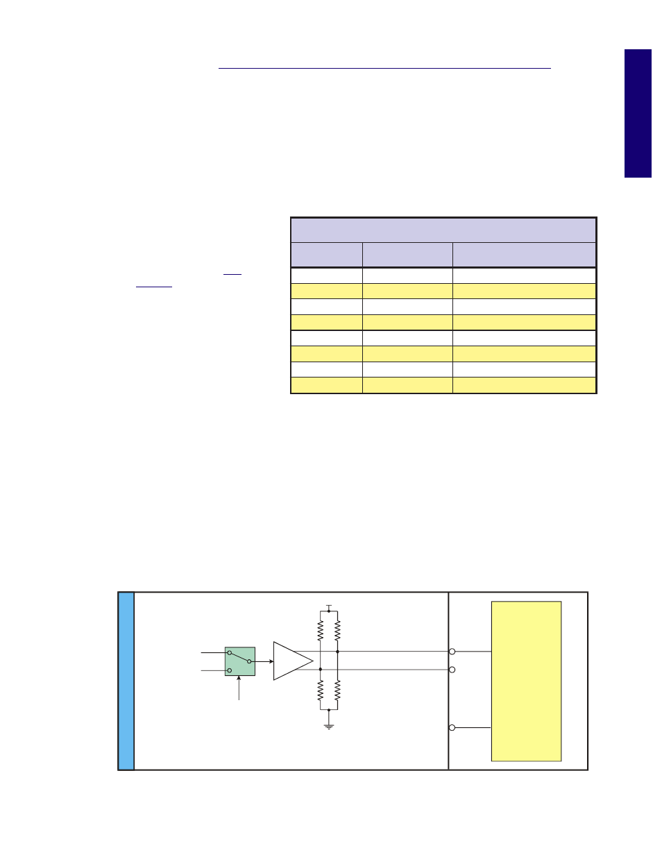
Output (+)
Output (+)
Output (-)
Step Clock
Secondary
Drive
Direction
+5VDC
Clock
User
Defined
Function
IOS
Hi
gh
S
p
e
ed D
if
fe
re
nt
ia
l I
/O
M
o
d
u
le
10k
Ω
4k
Ω
3.3k
Ω
20k
Ω
Figure 6.7: Differential I/O Output Equivalent Circuit
C o n f i g u r i n g a n
O u t p u t
The Differential I/O Group 10 has 3 Channels (Line Pairs 13 & 14, 15 & 16, and 17 & 18) that can be config-
ured as an output by the user and One Channel (Line Pairs 11 & 12) that is configured as output only. (SCK
and DIR on the Control Module.) These outputs can be configured as high speed outputs or 0 to 5VDC
general purpose outputs by using the IOS variable. The high speed clock outputs have the following
restrictions:
Line Pairs 11/12, 13/14 and 15/16 can be configured to Step Clock/Direction or Up/Down.
Line Pair 17/18 is limited to 1MHz Reference Out (17) and 10MHz Reference Out (18).