Modular l ynx system, Connect power to the lynx control module, Write a simple test program – Intelligent Motion Systems Modular LYNX System User Manual
Page 5
1 - 5
Modular L
YNX System
Modular LYNX System 12.05.2003
S e c t i o n 1
G e t t i n g S t a r t e d
S e c t i o n O v e r v i e w
The purpose of this section is to get you up and running quickly.
This section will help you do the following:
!
Connect power to the LYNX Control Module.
!
Connect and establish communications in single mode.
!
Write a simple test program.
G e t t i n g S t a r t e d
1234567
8
IM2000F
Yellow/Red-White
Red/Yellow-White
Orange/Black-White
Black/Orange-White
V+
GND
Current Adjust
Resistor*
*See Driver Documentation
for Current Adjust Resistor Value
Stepping
Motor
1234567
8
Step Clock
Direction
Opto Supply
ON
1
2
3
4
ON
1
2
3
4
Resolution Select Programmed
for 256 Resolution
)
DIR+
DIR-
SCK-
SCK+
GND
+5V
RX-
RX+
TX-
TX+
CGND
RX
TX
22
21
23
24
25
26
31
32
33
34
35
36
IG
INTELLIGENT MOTION SYSTEMS, INC.
FAULT
POWER
12
3
4
5
6
12
3
4
5
6
123
45
6
22
21
23
24
25
26
31
32
33
34
35
36
PGND
V+
TM
ISP200-4
AC Line (Black)
AC Neutral (White)
AC Ground (Green)
AC Line Cord
ISP200 - 4
IM483 Step Motor Driver
LYNX Control Module
Host PC
Ground (DB-9 = Pin 5)
TX (Transmit) (DB-9 = Pin 3)
RX (Receive) (DB-9 = Pin 2)
P2
P1
V+
GND
120VAC IN
RS-232 Communications Wiring
I n c l u d e d i n t h e P a c k a g e
(1) LYNX Control Module ........................................................ (IMS P/N LX-CM100 or 200-000)
(2) End Mounting Brackets ...................................................... (IMS P/N LX-EB100-000)
(1) IMS CD ............................................................................... (IMS P/N IMS-CD100-000)
(1) Screw Driver ...................................................................... (IMS P/N SD1)
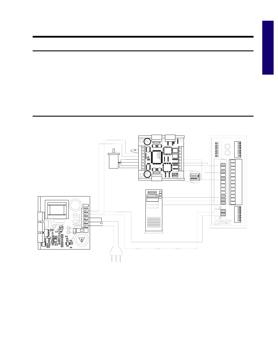
Figure 1.1: Basic Setup Configuration, RS-232 Interface