Modular l ynx system, Stepping motor – Intelligent Motion Systems Modular LYNX System User Manual
Page 37
1 - 37
Modular L
YNX System
Modular LYNX System 12.05.2003
DIR+
DIR-
SCK-
SCK+
GND
+5V
RX-
RX+
TX-
TX+
CGND
RX
TX
22
21
23
24
25
26
31
32
33
34
35
36
IG
123
45
6
1
2
3
456
12
3
4
5
6
22
21
23
24
25
26
31
32
33
34
35
36
GND
V+
A1
A0
A2
PT
HI
UG
TM
Motor Driver
Z
N
42
9D
G
P
5
962
7A
Z
N
42
9D
G
P
59
62
7
A
+5VDC Opto Supply
Step Clock Input
Direction Input
SCLK+
DIR+
+5VDC
OUTPUT
D
if
f
er
ent
ia
l
/
O
M
O
DU
L
E
TM
13+
13-
14-
14+
15-
15+
16-
16+
17-
17+
18-
18+
GD
HSIO
ENCODER
13+
Channel A
14+
Channel B
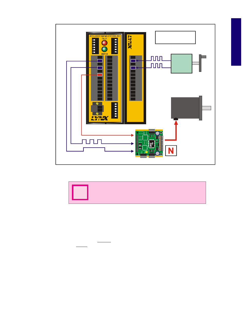
Stepping
Motor
Power Connections
Not Shown For
Simplification
Encoder or
Pulse Generator
Figure 6.9 Half Axis Mode (Following)
NOTE:
The HAS variable must be set to less than 1 or Error
Code 9004, “Ratio Out of Range” will occur.
N
O n e a n d a H a l f A x i s O p e r a t i o n ( R A T I O E )
A secondary drive can be connected to a pair of differential outputs. The secondary driver will operate off
of the differential output pair 15 and 16 (I/O pair 13 and 14 can also operate in this mode). Setting the
ratio mode to TRUE (1) for the differential output clock (IOS) specifies a secondary drive function. Then
when ratio mode is enabled (
RATIOE
); the secondary axis will follow the primary axis with the ratio
specified by the
RATIO
variable.
The sequence of commands used to make this setup function would be as follows:
‘Set IOS 15 to step/direction clock
type, and ratio mode
IOS 15 = 5,0,1,0,2,1
‘Set IOS 16 to step/direction clock
type, and ratio mode
IOS 16 = 6,0,1,0,2,1
‘Set Ratio Mode Enable Flag to
TRUE (1)