Isolated ground – Intelligent Motion Systems Modular LYNX System User Manual
Page 48
1 - 48
Modular LYNX System 12.05.2003
P i n A s s i g n m e n t s A n d D e s c r i p t i o n
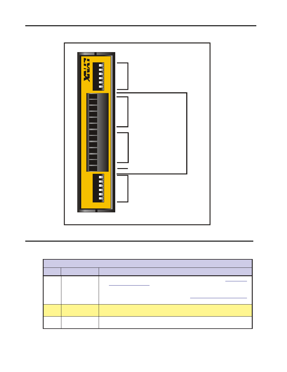
C o n n e c t i o n O v e r v i e w
12
3
4
5
6
42
41
43
44
45
46
12
3
4
5
6
51
52
53
54
55
56
IS
O
L
A
TE
D
I/
O
M
O
D
U
L
E
42
41
43
44
45
46
51
52
53
54
55
56
IG
TM
Group 40
Isolated I/O
Group 50
Isolated I/O
+5V Pullup Enable
Switches for
I/O Group 50
+5V Pullup Enable
Switches for
I/O Group 40
P1
Isolated Ground
Figure 9.2: Isolated Digital I/O Module Connection Overview
O
/
I
l
a
t
i
g
i
D
d
e
t
a
l
o
s
I
:
r
o
t
c
e
n
n
o
C
l
a
n
i
m
r
e
T
e
l
b
a
e
v
o
m
e
R
n
o
i
t
i
s
o
P
3
1
-
1
P
#
n
i
P
n
o
i
t
c
n
u
F
n
o
i
t
p
i
r
c
s
e
D
8
-
1
0
4
p
u
o
r
G
O
/
I
6
4
-
1
4
s
e
n
i
L
e
h
t
f
o
n
o
i
t
p
i
r
c
s
e
d
e
e
s
(
s
t
u
p
t
u
o
r
o
s
t
u
p
n
i
s
a
e
l
b
a
m
m
a
r
g
o
r
p
y
ll
a
u
d
i
v
i
d
n
i
e
r
a
s
l
a
n
g
i
S
d
n
a
m
m
o
c
S
O
I
e
h
t
n
i
c
n
e
r
e
f
e
R
e
r
a
w
t
f
o
S
:
3
t
r
a
P
d
n
a
e
l
b
i
t
a
p
m
o
c
l
e
v
e
l
c
i
g
o
l
S
O
M
C
e
r
a
s
t
u
p
n
I
.
)
l
a
u
n
a
m
s
i
h
t
f
o
e
n
e
p
o
e
r
a
s
t
u
p
t
u
O
.
g
n
i
r
e
t
l
i
f
l
a
t
i
g
i
d
a
i
v
e
l
b
a
l
i
a
v
a
s
i
n
o
i
t
c
e
j
e
r
e
s
i
o
N
.
s
t
l
o
v
4
2
o
t
s
t
u
p
n
i
t
p
e
c
c
a
n
a
c
n
a
c
s
t
u
p
t
u
O
.
C
D
V
5
o
t
s
r
o
t
s
i
s
e
r
p
u
ll
u
p
m
h
o
K
5
.
7
e
l
b
a
h
c
t
i
w
s
y
ll
a
u
d
i
v
i
d
n
i
e
v
a
h
h
c
a
e
s
O
/
I
.
n
i
a
r
d
o
t
r
e
f
e
R
.
s
d
a
o
l
t
n
e
c
s
e
d
n
a
c
n
i
r
o
e
v
i
t
s
i
s
e
r
,
e
v
i
t
c
u
d
n
i
h
c
t
i
w
s
O
/
I
l
a
t
i
g
i
D
e
h
t
g
n
i
r
u
g
i
f
n
o
C
:
6
n
o
i
t
c
e
S
.
s
n
o
i
t
a
c
i
f
i
c
e
p
s
d
n
a
e
g
a
s
u
r
o
f
2
1
-
7
0
5
p
u
o
r
G
O
/
I
6
5
-
1
5
s
e
n
i
L
.
e
v
o
b
a
n
o
i
t
p
i
r
c
s
e
d
e
e
S
3
1
d
n
u
o
r
G
O
/
I
d
e
t
a
l
o
s
I
d
n
a
r
e
w
o
p
e
h
t
m
o
r
f
d
e
t
a
l
o
s
I
.
O
/
I
0
5
d
n
a
0
4
s
p
u
o
r
g
r
o
f
n
r
u
t
e
r
l
a
n
g
i
s
n
o
m
m
o
c
d
e
t
a
l
o
s
I
.
s
d
n
u
o
r
g
n
o
i
t
a
c
i
n
u
m
m
o
c
Table 9.1: Isolated Digital I/O Module P1 Connector Pin Configuration