P1 p2 p3 – Intelligent Motion Systems Modular LYNX System User Manual
Page 44
1 - 44
Modular LYNX System 12.05.2003
P o w e r R e q u i r e m e n t s
C o n n e c t i o n O v e r v i e w
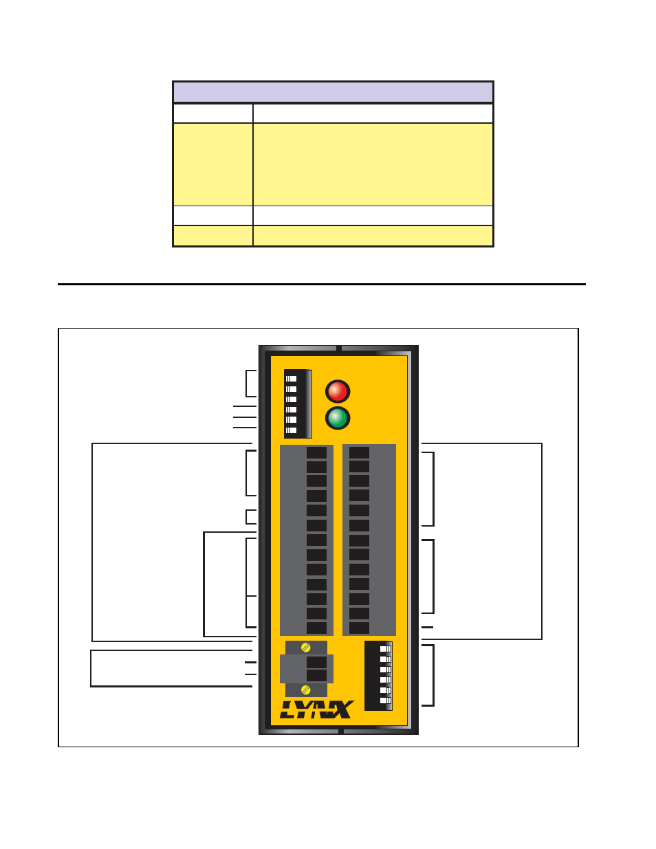
Figure 8.2: LYNX Control Module (Combination) Connections and Switches
Table 8.1: Power Requirements for the LYNX Control Module (Combination)
s
n
o
i
t
a
c
i
f
i
c
e
p
S
d
n
a
s
t
n
e
m
e
r
i
u
q
e
R
r
e
w
o
P
e
g
a
t
l
o
V
t
u
p
n
I
%
5
±
C
D
V
5
+
r
o
d
e
t
a
l
u
g
e
r
n
U
C
D
V
5
7
+
o
t
2
1
+
t
n
e
r
r
u
C
t
u
p
n
I
)
t
u
p
n
i
C
D
V
5
(
A
m
0
5
2
*
)
t
u
p
n
I
C
D
V
2
1
+
(
A
m
5
6
1
*
)
t
u
p
n
I
C
D
V
8
4
+
(
A
m
0
.
5
9
*
)
t
u
p
n
I
C
D
V
5
7
+
(
A
m
5
.
4
8
)
y
l
n
O
e
l
u
d
o
M
l
o
r
t
n
o
C
(
d
e
d
a
o
l
n
u
t
u
p
t
u
o
C
D
V
5
+
d
n
a
O
/
I
*
e
g
a
t
l
o
V
t
u
p
t
u
O
%
5
±
C
D
V
5
+
t
n
e
r
r
u
C
t
u
p
t
u
O
d
e
t
i
m
i
L
y
ll
a
n
r
e
t
n
I
(
A
m
0
5
1
DIR+
DIR-
SCK-
SCK+
GND
+5V
RX-
RX+
TX-
TX+
CGND
RX
TX
13+
13-
14-
14+
17-
17+
21
22
23
24
25
26
IG
12
3
4
5
6
12
3
4
5
6
21
22
23
24
25
26
GND
V+
A1
A0
A2
PT
HI
UG
TM
ON
ON
ON
Party Mode Address
Switches Select Addresses
"A" through "G"
Party MOde Select
Host INterface Mode Select
Software Upgrade
Differential Direction I/O 11
and Step Clock (I/O 12) Outputs
Current Limited +5V Output
or +5V Power In
Serial
Communications
RS-485
RS-232
Power Ground
+12 to +75 VDC Input Power
Group 10
Differential I/O
Channels 13, 14,
and 17
Group 20
+5 to +24 VDC I/O
Isolated Ground
+5 V Pullup Enable
Switches for
I/O Group 20
P1
P2
P3
INTELLIGENT MOTION SYSTEMS, INC.
FAULT
POWER