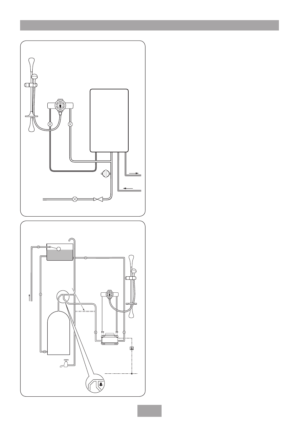
Typical suitable installations, B) pump assisted gravity fed systems, C) unvented mains pressure showers – HP COMBI 2180206H User Manual
Page 6
Combi HP thermostatic mixer shower
a) Instantaneous gas-heated showers,
e.g. combination boilers
(fig.)
The shower control MuST be installed with a
multipoint gas water heater or combination
boiler of a fully modulating design (i.e. where
the water draw-off rate indirectly controls the
gas flow to the burner). A drop tight pressure
reducing valve MuST be fitted if the supply
pressures exceed 5 bar maintained.
An expansion vessel (shown in fig.) MuST be
fitted, and regularly maintained, to make sure
the unit is not damaged by excess pressures.
This may already be installed within the boiler
(check with manufacturer) and is in addition to
the normally larger central heating expansion
vessel.
The layout and sizing of pipework must be
such that nominally equal inlet supply pressures
are achieved and the effects of other draw-offs
are minimised. The hot supply temperature
MuST remain a minimum of 10°c hotter than
the required blend temperature for the best
performance.
b) Pump assisted gravity fed systems
(fig.)
The pump MuST be fed from a cold water
cistern and hot water cylinder providing
nominally equal pressures. The pump must be
capable of maintaining a minimum running
pressure of 1 bar.
c) Unvented mains pressure showers
(fig.)
The shower control can be installed with an
unvented, stored hot water cylinder.
For systems with no cold water take off after the
appliance reducing valve, it will be necessary to
fit an additional drop tight pressure reducing
valve when the mains pressure is over 5 bar. The
drop tight pressure reducing valve MuST be
set at the same value as the unvented package
pressure reducing valve.
Note: An additional expansion vessel (fig.)
may be required if a second pressure reducing
valve is installed. This does not apply to
TyPIcAl SuITABlE InSTAllATIOnS
TYPICAL SUITABLE INSTALLATIONS
T00221
CH flow
Cold
mains
supply
Hot water
Expansion
vessel
CH return
Service
valves
Shower
mixer
valve
Stop tap
Pressure
reducing valve
Combination
boiler
Fig.
diagrammatic view (not to scale)
T00222
Hot water
cylinder
Cold supply
Hot
supply
Cold
water
mains
supply
Drain
valve
Gate
valve
Cold water
cistern
Other
draw-offs
Draw-off must point
down to avoid airlock
issues
Ring main
Isolating switch
or pull cord
switch (both
fused at 3A)
Alternative
supply
(must be
below
vent pipe tee)
Service
valve
Service
valve
Stop valve
Mixer
Valve
Riser
rail
Pump
Fig.
diagrammatic view (not to scale)