F. wall switch installation for fan (optional), E. junction box installation, D. electrical service and repair – Heat & Glo Fireplace 8000CL-IPI-S User Manual
Page 52
Heat & Glo • 6000CL-IPI-S, 6000CL-IPI-T, 8000CL-IPI-S 8000CL-IPI-T • 2165-900 Rev. S • 9/12
52
F. Wall Switch Installation for Fan (Optional)
If the box is being wired to a wall mounted switch for use
with a fan (See Figure 12.3):
• The power supply for the appliance must be brought into
a switch box.
• The power can then be supplied from the switch box to the
appliance using a minimum of 14-3 with ground wire.
• At the switch box connect the black (hot) wire and red
(switch leg) wire to the wall switch as shown.
• At the appliance connect the black (hot), white (neutral)
and green (ground) wires to the junction box as shown.
• Add a 1/4 in. insulated female connector to the red (switch
leg) wire, route it through the knockout in the face of the
junction box, and connect to the top fan switch connector
(1/4 in. male) as shown.
WHT
WHT
BLK
BLK
GRN wire
inside box
Copper
ground attached
to GRN screw with
GRN wire
14/2WG
Cover Plate
outside firebox
Romex
Connector
Figure 12.2 Junction Box Detail
NOTICE: DO NOT wire
110 VAC to wall switch.
Red
Switch
Switch Box
Red
Black
Black
Green
Green
White
Power
Supply
Wires
White
R
ed
B
la
ck
G
re
en
W
hi
te
Minimum 14-3 AWG
with Ground
Junction Box
Knockout
Figure 12.3 Junction Box Wired to Wall Switch or BC10
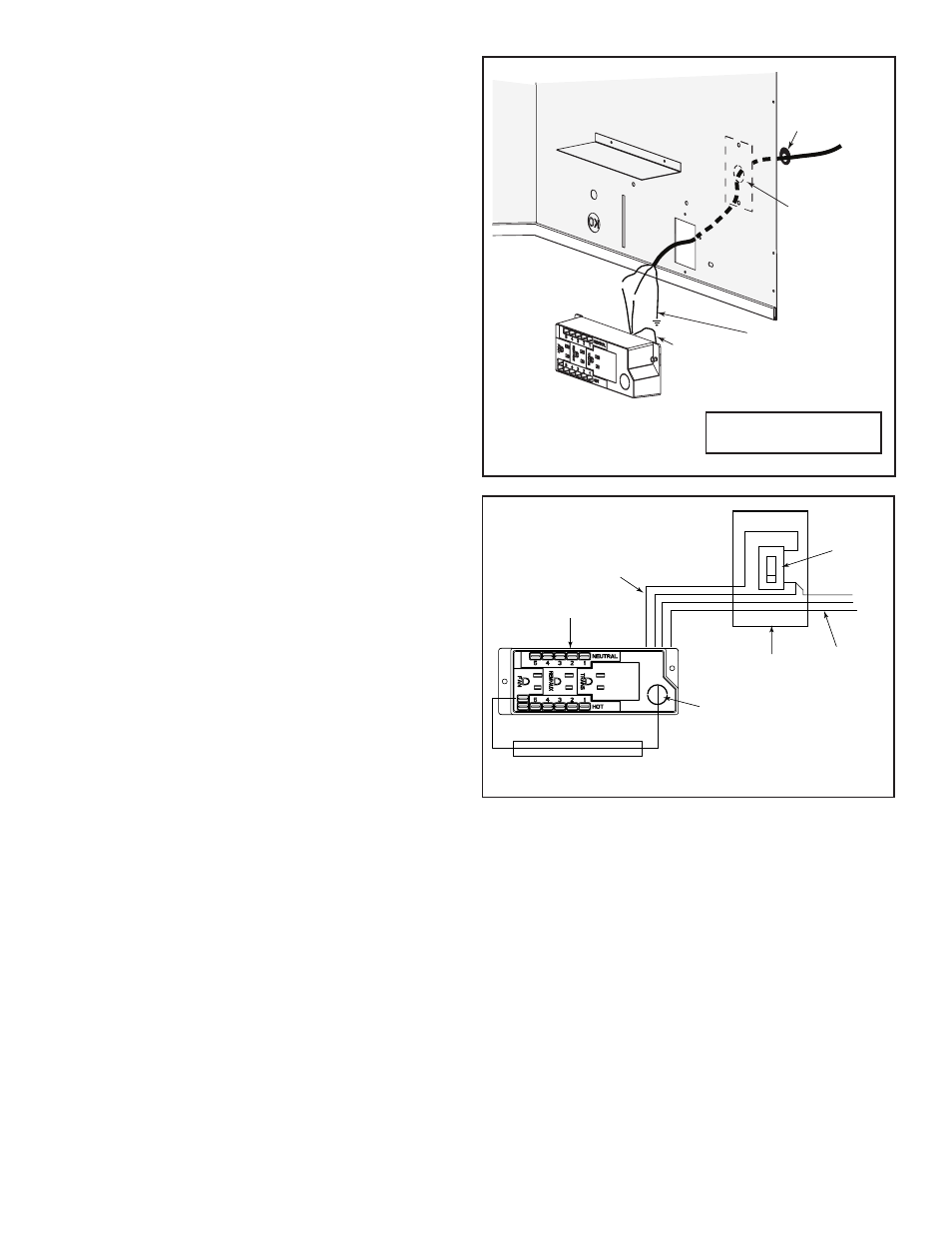
E. Junction Box Installation
If the box is being wired from the
INSIDE of the appliance:
• Remove the screw attaching the junction box/receptacle to
the outer shell, rotate the junction box inward to disengage
it from the outer shell (see Figure 12.2).
• Pull the electrical wires from outside the appliance through
the opening into the valve compartment and secure wires
with a Romex connector. See Figure 12.2.
• Make all necessary wire connections to the junction box/
receptacle and reattach the junction box/receptacle to the
outer shell.
D. Electrical Service and Repair
WARNING! Risk of Shock! Label all wires prior to dis-
connection when servicing controls. Wiring errors can
cause improper and dangerous operation. Verify proper
operation after servicing.
WARNING! Risk of Shock! Replace damaged wire with
type 105º C rated wire. Wire must have high temperature
insulation.