Maintenance replacement procedures, Step action, Remove power from the controller – Honeywell UMC800 User Manual
Page 80: Replace the fuse with the proper size and type, Cpu battery location fuse holder, Power supply cpu module
Maintenance
Replacement Procedures
72
UMC800 Controller Installation and User Guide
Release F
4/01
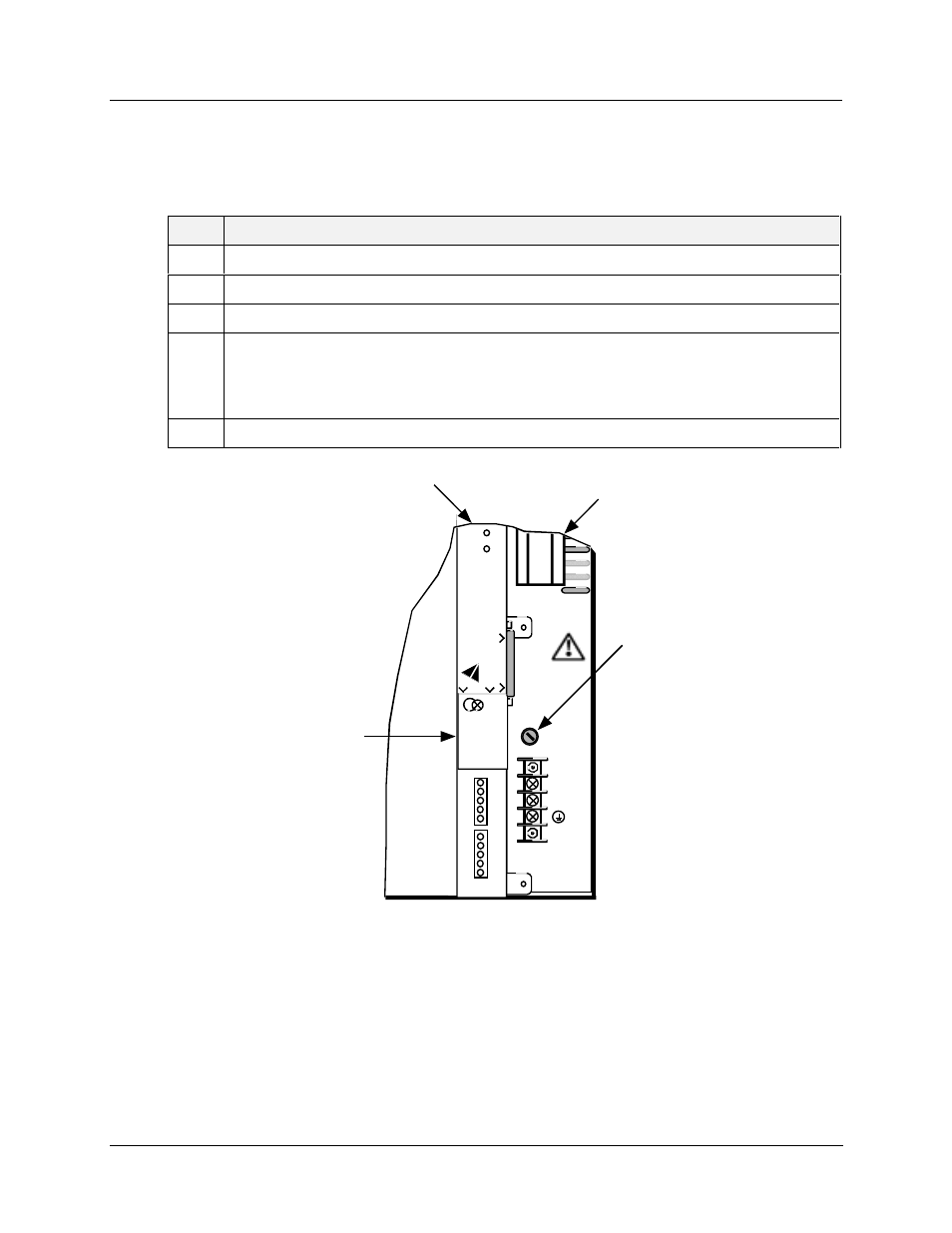
Replacing the power supply fuse
The power supply input circuit is protected with a fuse. Use the steps in the table below to replace the fuse
on the power supply module.
Step
Action
1
Remove power from the controller.
2
Locate the fuse holder located on the power supply module. See Figure 36.
3
Using a slotted screwdriver, remove the fuseholder cap by rotating it counterclockwise.
4
Replace the fuse with the proper size and type.
•
For 100-240 V supply: Size 5x20, F 3.15 A Time Delay 250 V, or equivalent.
•
For 24 V supply: Size 5x20, 6.3 A Slow Blow, or equivalent.
5
Replace the cap by pressing in and rotating it clockwise with the screwdriver.
_
100 - 24 0 V ~
50 / 60 Hz
100 VA MAX.
F 3,15 A T
250V
L1
L2 / N
CPU Battery
Location
Fuse Holder
POWER
LoBAT
FORCE
RUN
DIS
PL
A
Y
BAT
CO
M
M
B
CO
M
M
A
R
e
pl
ac
e ba
tt
e
ry
w
it
h
Ta
di
ra
n
T
L
51
01
/S
on
ly
.
U
s
e
o
f
a
n
o
th
er
ba
tte
ry
m
a
y
pr
e
s
e
nt
a
ris
k
o
f
fi
re
o
r e
x
pl
osi
on
.
S
e
e us
e
rs
g
ui
de
f
o
r i
ns
tr
uct
io
n
s
.
Power
Supply
CPU
Module
Figure 36 Power supply fuse and CPU battery location