Equipment identification, Controller components, Figure 2 umc800 controller hardware – Honeywell UMC800 User Manual
Page 13: Equipment identification controller components
Equipment Identification
Controller Components
Release F
UMC800 Controller Installation and User Guide
5
4/01
Equipment Identification
Controller Components
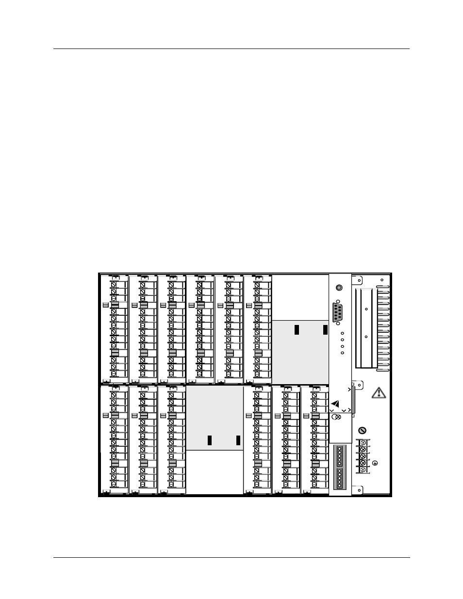
Enclosure
The UMC800 controller illustrated in Figure 2 consists of a single metal enclosure that houses the
following controller components:
•
Power supply module that plugs into the controller common backplane.
•
CPU module with two serial communications ports. An optional communications board provides two
RS485 serial communication ports (slave and master) that support Modbus® RTU protocol.
•
Backplane assembly capable of supporting up to 16 input or output modules.
•
Various types of I/O processing modules that plug into the common backplane.
•
Removable terminal blocks that connect the I/O modules with the field wiring.
•
Battery back-up power for RAM and real time clock in the event of power interruption.
12
11
10
9
8
7
6
5
4
3
2
1
12
11
10
9
8
7
6
5
4
3
2
1
12
11
10
9
8
7
6
5
4
3
2
1
_
100 - 240 V
~
50 / 60 Hz
100 VA MAX.
F 3,15 A T
250V
L1
L2 / N
12
11
10
9
8
7
6
5
4
3
2
1
12
11
10
9
8
7
6
5
4
3
2
1
12
11
10
9
8
7
6
5
4
3
2
1
12
11
10
9
8
7
6
5
4
3
2
1
12
11
10
9
8
7
6
5
4
3
2
1
12
11
10
9
8
7
6
5
4
3
2
1
12
11
10
9
8
7
6
5
4
3
2
1
12
11
10
9
8
7
6
5
4
3
2
1
12
11
10
9
8
7
6
5
4
3
2
1
POWER
LoBAT
FORCE
RUN
DI
S
P
L
A
Y
BAT
CONF
IG
URAT
ION
OFFLINE
RUN
PROGRAM
CO
M
M
B
CO
M
M
A
R
e
p
lac
e
bat
te
ry
w
it
h
T
adi
ra
n
TL510
1/
S
onl
y
.
U
s
e
of
an
ot
her
ba
tt
er
y
m
a
y
pr
ese
n
t a r
is
k
of
f
ir
e
or
ex
pl
osi
o
n
.
S
e
e
us
er
’s
gu
id
e
f
o
r i
n
s
tr
u
ct
io
ns
.
Figure 2 UMC800 controller hardware