Specifications, Centronics parallel pinout information – HP 2500C Series User Manual
Page 18
Product Information
1-10
Specifications
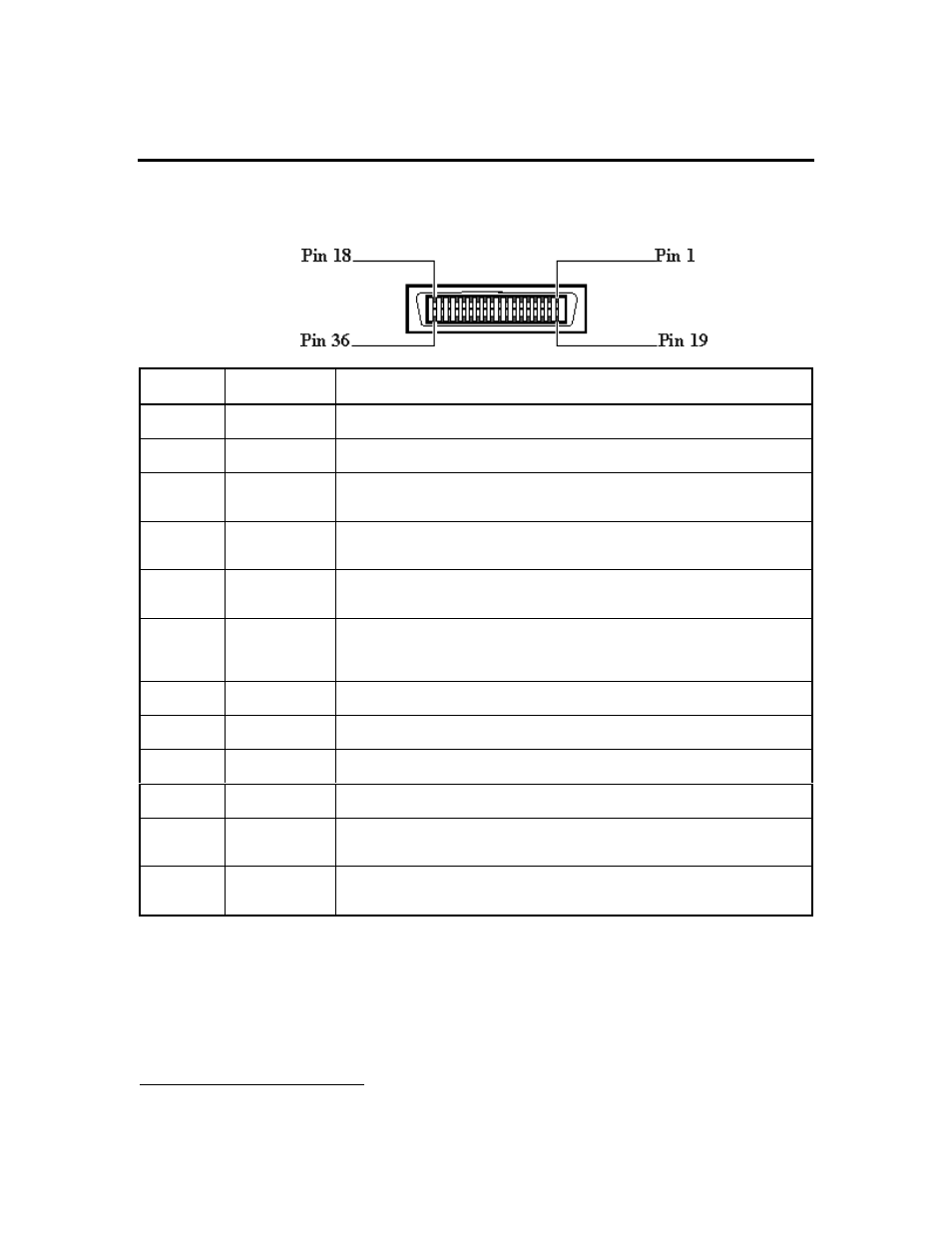
Centronics Parallel Pinout Information
P
IN
N
UMBER
P
IN
ID
D
ESCRIPTION
1
Strobe
1
A low pulse causes the printer to read one byte of data
2 - 9
Data 0 - Date 7
These pins are the data lines. Data 0 is the least significant bit (LSB)
10
Acknowledge
The printer sends a low pulse to indicate that it has accepted a byte of data and is
ready for more data.
11
Busy
The printer sends a high logic level to indicate to the computer that it cannot
receive data due to data entry, a full buffer or error status.
12
Paper Error
The printer sends a high logic level to indicate to the computer that it is out of
paper.
13
Ready
The printer sends a high logic level to indicate to the computer that it is in an online
condition. The printer sends a low logic level to indicate that it is offline or that the
input buffer is full.
16
Signal Ground
Signal interface ground.
17
Chassis Ground
Chassis ground.
18
+5 V
The printer outputs a +5 volt high logic level through a 2.2K ohm resistor.
19 - 30
Ground
These pins are tied to signal ground
31
Reset/Input
Clear
1
A low pulse sent by the computer resets the printer and clears the print buffer. The
reset occurs on the trailing edge of the pulse
32
Error
1
The printer sends a low logic level to the computer to indicate that it is in an error
state.
1
Active low