Step 9. wiring the fireplace – Heat & Glo Fireplace 6000TR-OAK User Manual
Page 26
Heat & Glo • 6000TR-OAK, 6000TR-OAK-IPI • 383-901 Rev. K • 5/06
30
Step 9. Wiring the Fireplace
NOTE: Electrical wiring must be installed by a licensed
electrician.
CAUTION: DISCONNECT REMOTE CONTROLS IF AB-
SENT FOR EXTENDED TIME PERIODS. THIS WILL PRE-
VENT ACCIDENTAL FIREPLACE OPERATION.
For Standing Pilot Ignition Wiring
Appliance Requirements
• This appliance DOES NOT require 110-120 VAC to operate.
WARNING: DO NOT CONNECT 110-120 VAC
TO THE GAS CONTROL VALVE OR THE AP-
PLIANCE WILL MALFUNCTION AND THE
VALVE WILL BE DESTROYED.
!
!
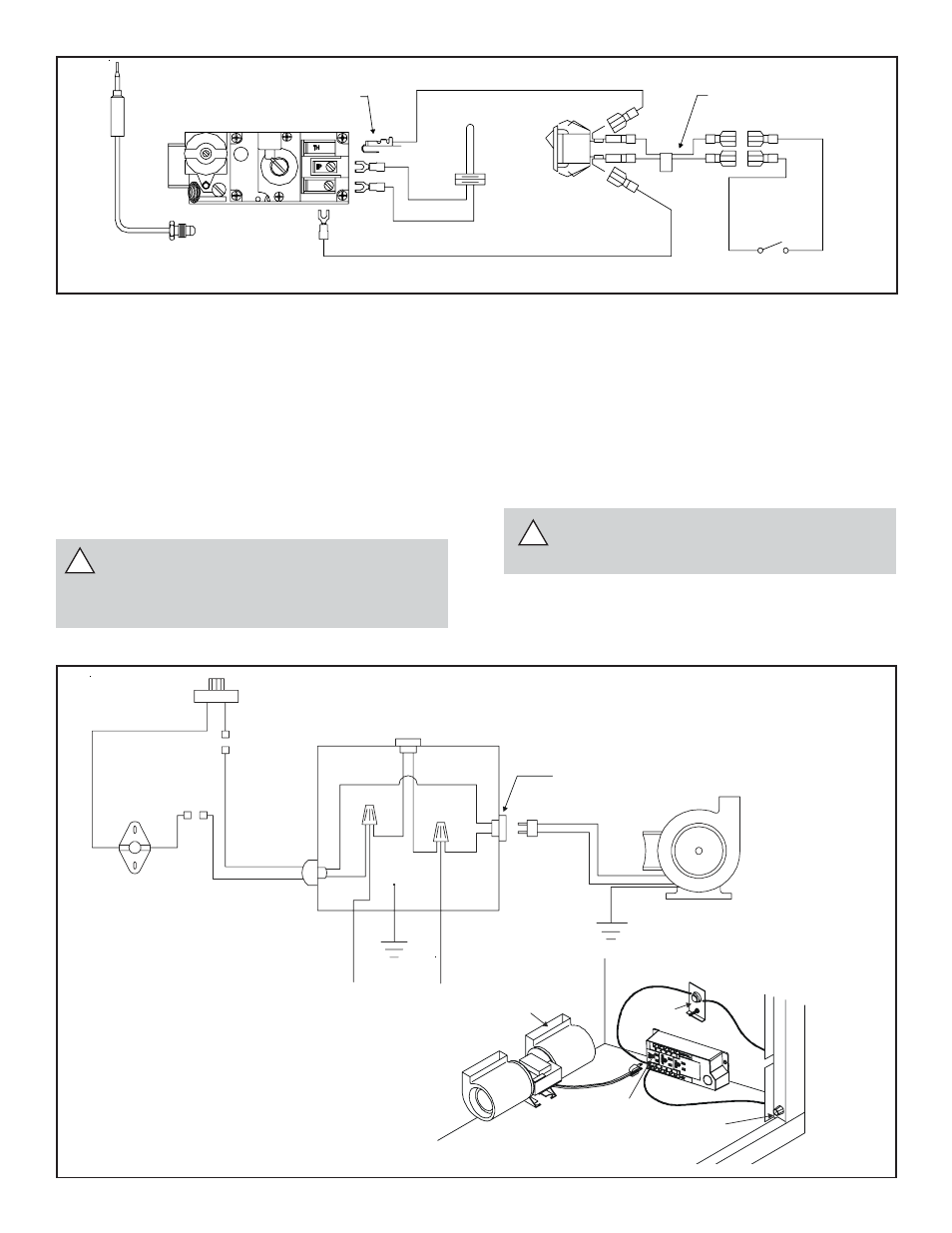
Figure 35. Standing Pilot Ignition Wiring Diagram
Figure 36. Fan Wiring Diagram
Optional Accessories
Optional fan and remote control kits require that 110-120
VAC be wired to the factory installed junction box before
the fireplace is permanently installed.
Wall Switch
Position the wall switch in the desired position on a wall.
Run a maximum of 25 feet (7.8 m) or less length of 18
A.W.G. minimum wire and connect it to the fireplace ON/
OFF switch pigtails.
WARNING: DO NOT CONNECT 110-120 VAC
TO THE WALL SWITCH OR THE CONTROL
VALVE WILL BE DESTROYED.
CAUTION: LABEL ALL WIRES PRIOR TO DISCONNEC-
TION WHEN SERVICING CONTROLS. WIRING ERRORS
CAN CAUSE IMPROPER AND DANGEROUS OPERATION.
VERIFY PROPER OPERATION AFTER SERVICING.
BLACK S2
ON
OFF
ON/OFF
SWITCH
WHITE T2
RED T1
THERMOPILE
GAS VALUE
BLACK S1
3/16” PIGGYBACK CONNECTOR
THERMOCOUPLE
REMOTE SWITCH
PIGTAIL
OPTIONAL WALL SWITCH,
THERMOSTAT OR REMOTE
NOTE: IF ANY OF THE ORIGINAL WIRE
AS SUPPLIED WITH THE APPLIANCE
MUST BE REPLACED, IT MUST BE
REPLACED WITH TYPE 105 C RATED WIRE.
O
JUNCTION BOX
VARIABLE SPEED CONTROL
TEMPERATURE
SENSOR SWITCH
WHT
GRN
BLK
BLK
110-120 VAC
BLOWER
BLOWER RECEPTACLE
BLK
BLK
BLK
BLK
WHT
GROUND
WHT
BLK
BLK
BLK
BLOWER
SENSOR
SWITCH
“FAN”
RECEPTACLE
SPEED
CONTROL