D. optional led lighting circuit, E. electrical service and repair, F. junction box installation – Heat & Glo Fireplace RED40ST User Manual
Page 45: For models with led lighting option only
Heat & Glo • RED40, RED40ST • 2155-900 Rev. P
• 10/12
45
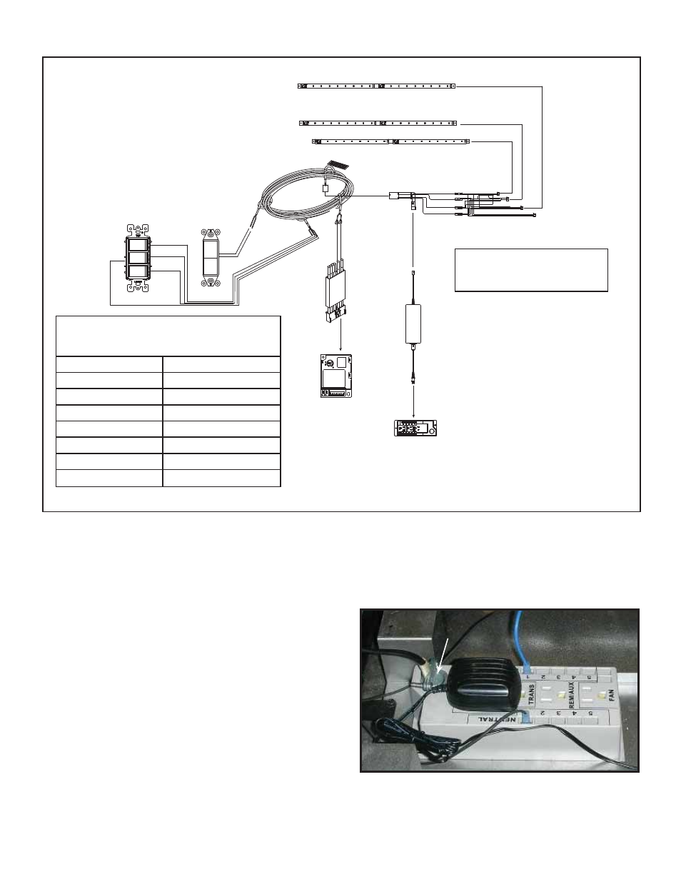
D. Optional LED Lighting Circuit
POWER SUPPLY
LED LIGHTBAR
ASSEMBLY
6 LEAD WALL CONTROL WIRE
APPLIANCE
ON/OFF
CONTROL
WIRE ASSEMBLY
HOT
NEUTRAL
JUNCTION BOX
IGNITION
MODULE 3 VAC
I
S
PLUG IN
PLUG IN
PLUG IN
BRN
LIGHT
CONTROL
ORANGE
YELLOW
GREEN
RED
BRN
BRN
NOT USED FOR THIS MODEL
RED
BRN
L.E.D CONTROL
HARNESS
2 1
BLK
Figure 12.6 LED Wiring Diagram
For models with LED lighting option only.
NOTE: The chart below show the colors produced
when light control is wired and orientated as shown
in this wiring diagram.
SWITCH TRIPPED
COLOR PRODUCED
YELLOW
GREEN
ORANGE
RED
GREEN
BLUE
YEL/ORG/GRN
WHITE/CLEAR
YEL/ORG
YELLOW
ORG/GRN
PURPLE
YEL/GRN
LIGHT BLUE
NOTE: Harness wire colors
are subject to change
without notice.
3. Make the connection inside the junction box to the 120V
wire. Connect green to the ground nut, black to black,
and white to white.
4. To reattach the junction box, insert one end of the
junction box in the slot provided and securely screw the
other end of the junction box to the control tray panel.
E. Electrical Service and Repair
WARNING! Risk of Shock! Label all wires prior to dis-
connection when servicing controls. Wiring errors can
cause improper and dangerous operation. Verify proper
operation after servicing.
WARNING! Risk of Shock! Replace damaged wire with
type 105° C rated wire. Wire must have high temperature
insulation.
F. Junction Box Installation
WARNING! Risk of Shock! Label all wires prior to dis-
connection when servicing controls. Wiring errors can
cause improper and dangerous operation. Verify proper
operation after servicing.
WARNING! Risk of Shock! Replace damaged wire with
type 105° C rated wire. Wire must have high temperature
insulation.
1. Remove the one screw that secures the junction box to
the control tray panel.
2. Route the wire through the strain relief in the outer wrap
and down through the knockout located on top side of
the junction box. See Figure 12.7.
Figure 12.7 Junction Box Detail
In the event that the junction box may need to be ac-
cessed or installed after fi nish methods have been ap-
plied, access is possible by removing the valve assembly
(See Figure 11.2).
KNOCKOUT
KNOCKOUT