C. gas connection, D. high altitude installations – Heat & Glo Fireplace RED40ST User Manual
Page 42
Heat & Glo • RED40, RED40ST • 2155-900 Rev. P • 10/12
42
C. Gas Connection
• Refer to Reference Section 16 for location of gas line
access in appliance.
• Gas line may be run through either side of appliance.
• The gap between supply piping and gas access hole
may be caulked with caulk with a minimum of 300ºF
continuous exposure rating or stuffed with non-
combustible, unfaced insulation to prevent cold air
infi ltration.
• Ensure that gas line does not come in contact with outer
wrap of the appliance. Follow local codes.
• Pipe incoming gas line into valve compartment.
• Connect incoming gas line to the 1/2 in. (13 mm)
connection on manual shutoff valve.
WARNING! Risk of Fire or Explosion! Support control
when attaching pipe to prevent bending gas line.
• A small amount of air will be in the gas supply lines.
WARNING! Risk of Fire or Explosion! Gas build-up dur-
ing line purge could ignite.
• Purge should be performed by qualified service
technician.
• Ensure adequate ventilation.
• Ensure there are no ignition sources such as sparks
or open fl ames.
Light the appliance. It will take a short time for air to purge
from lines. When purging is complete the appliance will
light and operate normally.
WARNING! Risk of Fire, Explosion or Asphyxiation!
Check all fi ttings and connections with a non-corrosive
commercially available leak-check solution. DO NOT use
open fl ame. Fittings and connections could have loos-
ened during shipping and handling.
WARNING! Risk of Fire! DO NOT change valve settings.
This valve has been preset at the factory.
D. High Altitude Installations
NOTICE: If the heating value of the gas has been reduced,
these rules do not apply. Check with your local gas utility
or authorities having jurisdiction.
When installing above 2000 feet elevation:
• In the USA: Reduce burner orifi ce 4% for each 1000 feet
above 2000 feet.
• In CANADA: Reduce burner orifi ce 10% for elevations
between 2000 feet and 4500 feet. Above 4500 feet,
consult local gas utility.
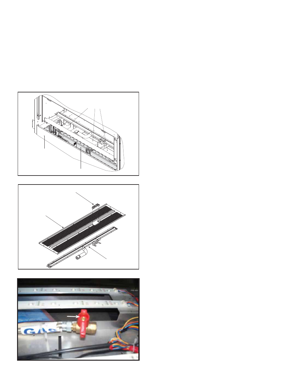
Figure 11.4 Gas Fitting Access
Figure 11.2 Gas and Electrical Access
ACCESS PANEL
(For use prior to finishing)
OUTER ACCESS PANEL TRAY
(For use after finishing)
INNER ACCESS WINDOWS
(FOR USE AFTER FINISHING)
Figure 11.3. Base Pan with Burner and Pilot Cover
2. Remove the base pan. It is attached with 10 screws to
the interior fi rebox bottom and with 12 screws to the
burner assembly. If your appliance is a model that has
the glass rock media, you must also remove the pilot
shield cover at this time. See Figure 11.2 and Figure
11.3.
3. Remove the two screws securing the burner to the
fi rebox sides and disengage burner from over orifi ce.
Remove burner. See Figure 11.3.
4. Remove access panel covers or glass windows, along
with gaskets. Gaskets may be fragile. Handle with
care. See Figure 11.2.
BURNER ASSEMBLY
INNER BASE PAN TRAY
PILOT SHIELD
(INSTALLED ON MODELS WITH LIGHT MEDIA OPTION)
GAS SHUT OFF VALVE
GAS SHUT OFF VALVE