Warning, B. vent components diagrams (continued) – Hearth and Home Technologies DV3732SBIL User Manual
Page 70
Hearth & Home Technologies • DV3732SBI, DV3732SBIL • 2215-900 Rev. G • 2/13
70
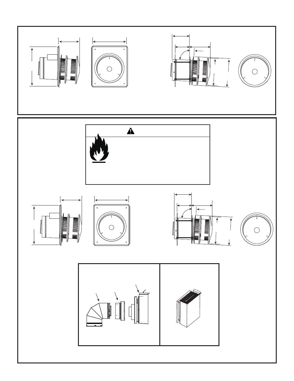
B. Vent Components Diagrams (continued)
13 in.
(330 mm)
15 in.
(381 mm)
8-1/8 in.
(206 mm)
10-7/8 in.
276 mm
10-1/2 in.
267 mm
3°
87°
Effective Length
5-3/4 to 8-3/8 in.
146 to 213 mm
5-1/2 in.
140 mm
8-3/8 in.
213 mm
Figure 16.6 DVP vent components
DVP-HRC-SS
DVP-HRC-ZC-SS
HORIZONTAL TERMINATION CAP
Figure 16.7 SLP Series Vent Components
Fire Risk.
• When using SLP-HRC-SS and SLP-HRC-ZC-
SS termination caps on top vented fi replaces,
a one foot minimum vertical vent section is
required before installing fi rst elbow.
WARNING
13 in.
(330 mm)
15 in.
(381 mm)
8-1/8 in.
(206 mm)
10-7/8 in.
276 mm
10-1/2 in.
267 mm
3°
87°
Effective Length
5-3/4 to 8-3/8 in.
146 to 213 mm
5-1/2 in.
140 mm
8-3/8 in.
213 mm
SLP-HRC-SS
SLP-HRC-ZC-SS
HORIZONTAL TERMINATION CAP
• When using DVP-TB1 termination cap on top vented
fi replaces, a three foot minimum vertical vent section is
required before installing fi rst elbow.
DVP-TB1
HORIZONTAL TERMINATION CAP
SLP90
SL-2DVP
DVP-TB1
DVP-TB1
ASSEMBLY