Hustler Turf Lawn Mower User Manual
Page 93
Park brake spring adjustment
Occasionally check the park brake spring adjustment using the following
method:
1. Shut engine off, place control levers in the park brake position,
disengage deck clutch, remove ignition switch key and disconnect
negative battery cable before doing any adjustments.
2. Position the control lever in the neutral position.
3. Make sure the brake actuator lever and the brake link are all the way
down. Fig. 9-28
4. Tighten the nylock nut on top of the spring assembly until it is
touching the top flat washer. Do not compress the spring. Fig. 9-29
5. Place the control lever in the park brake position. The brake pawl
should now be activated and engaging the integrated pump/motor
brake gear. Fig. 9-30
6. Repeat steps 2 thru 4 for the other side.
Park brake switch adjustment
Occasionally the park brake switch may need adjustment. Use the
following method to adjust the switch:
1. Park the unit on a flat surface. Stop the engine and remove the
ignition key. Place control levers in the park brake position.
2. Loosen the screws holding the switch. Fig. 9-28
3. Slide the switch all the way down until it is fully activated (button
pushed in) against the brake actuator lever.
4. Tighten the screws.
Hydraulic pump belt adjustment
The pump drive belt tension remains constant by means of a tension idler
and spring (Fig. 9-31). There is no tension adjustment of this belt. NOTE:
Inspect the belt every 100 hours and replace as needed. Replace the
belt every 200 hours or every two (2) years whichever comes first.
WARNING: If the pump belt fails, loss of control will occur
especially when operating on a slope. If you lose steering
control while operating the machine, place the steering
control levers in the park brake position immediately.
Inspect the machine and involve your Hustler dealer to
resolve the problem before continuing to operate.
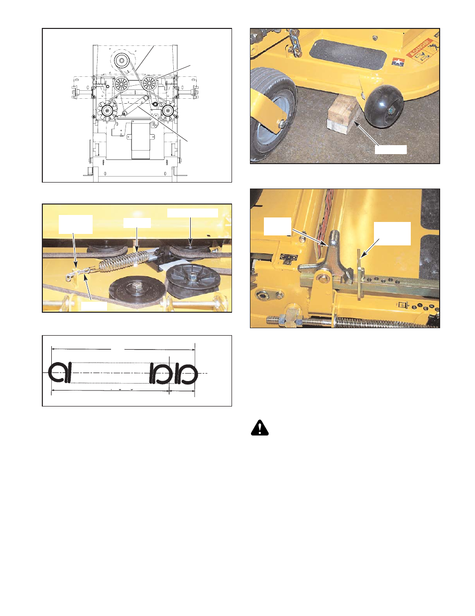
Deck drive belt adjustment
The spindle belt tension remains constant by means of a tension idler and
spring (Fig. 9-32). The spring tension should be such that the belt does not
slip under normal operating load conditions, assuming the belt is not
excessively worn or damaged. As belt stretches and wears in, adjustment
may become necessary. To increase belt tension, move the spring chain
one (or more) link(s) at the anchor bracket (Fig. 9-32). Installed spring
length should be 7.50" ± .3" (19.05 cm ± .76 cm) originally with
adjustments of .60" (15.2mm) per chain link. (Fig. 9-32 & 9-33)
IMPORTANT: Do not over tension the spring to compensate for a
badly worn belt or pulley.
Engine RPM setting
The FasTrak 44/52 is designed so that the engine will run at 3400 rpm
with integrated pump/motor load only. At this speed the integrated
pump/motors are running at their maximum rated speed.
Figure 9-35
Height
adjusting
stop
Stop
handle
Figure 9-34
Blocks
Figure 9-31
Spring
Tension
idler
Pump drive
belt
Figure 9-32
Spring
Tension idler
Chain
Anchor
bracket
Figure 9-33
1.50”
Spring Extension
7.50”
6.0”
Normal Spring Length
365262
4/07
9-17