Adjustments – Hustler Turf Lawn Mower User Manual
Page 91
ADJUSTMENTS
Introduction
Your FasTrak 44/52 was adjusted before it left the factory and was
checked during predelivery setup. However, after start-up and continued
use, a certain amount of break-in wear will cause some adjustments to
change.
Remain alert for unusual noises, they could be signaling a problem.
Visually inspect the machine for any abnormal wear or damage. A good
time to detect potential problems is while performing scheduled
maintenance service. Correcting the problem as quickly as possible is the
best insurance.
Clear away heavy build-up of grease, oil and dirt, especially in the
engine and under the seat platform areas; minute dust particle are abrasive
to close-tolerance engine and hydraulic assemblies.
Some repairs require the assistance of a trained service mechanic and
should not be attempted by unskilled personnel. Consult your Hustler
service center when assistance is needed.
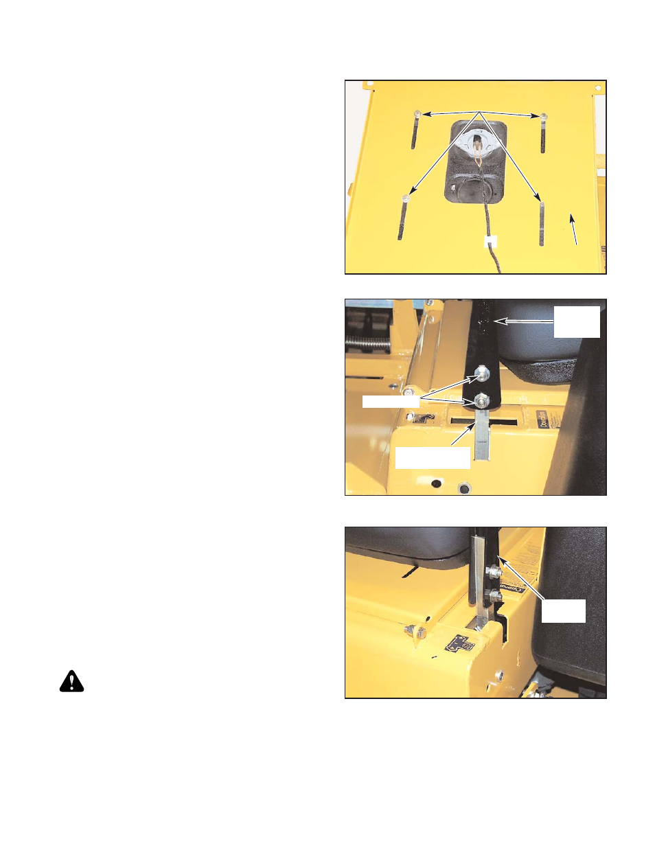
Seat adjustment
The seat can be adjusted forward and rearward by removing the two cap
screws that lock the seat platform in place and pivoting the seat platform up
and forward. Then loosen the four cap screws on the underneath side of the
operator’s platform. Position the seat where you have the best control of
the machine and are the most comfortable and then tighten the cap screws.
Fig. 9-23
Control lever adjustment
The control levers can be adjusted for operator comfort. By loosening
the cap screws that attaches the upper control lever to the lower lever (Fig.
9-24), the upper control lever can be pivoted to fit the operator’s personal
preference.
The control levers can also be adjusted up and down. Remove the cap
screws and slide the upper control lever up or down and align the holes in it
with the holes in lower lever. Re-install the cap screws and tighten.
The control levers should be adjusted so that they align with each other
when in the neutral position.
Steering linkage
The neutral adjustment for the control levers in the neutral position is
discussed in this section.
The tractor steering has been factory adjusted to eliminate creeping
when the control levers are in the neutral position (Fig. 9-25). However,
should the tractor begin to creep, the control lever linkage can be adjusted
as follows:
Control Lever Neutral Adjustment
Before considering any adjustment, check the tire air pressure. Unequal
tire pressure will cause the tractor to drift to one side. Refer to tire pressure
information in the Maintenance section of this manual.
Fine adjustment to the unit’s steering is made with the adjustable pump
linkage rods. Fig. 9-26
Neutral is properly adjusted when the control levers are in the neutral
position and the drive wheels are not turning.
If the tractor creeps in the neutral position the control linkage may be
adjusted as follows:
1. Raise and block the tractor up so the drive wheels are off of the
floor.
WARNING: Never work under the machine or attachment
unless it is safely supported with jack stands. Make certain
machine is secure when it is raised and placed on the jack stands.
The jack stands should not allow the machine to move when the
engine is running and the drive wheels are rotating. Use only
certified jack stands. Use only appropriate jack stands, with a
minimum weight rating of 2000 pounds to block the unit up. Use
in pairs only. Follow the instructions supplied with the vehicle
stands.
2. Position the control lever in the neutral position. Disengage the
deck clutch switch Fig. 9-25.
3. Loosen the nut on the steering dampener’s rear ball stud. Fig. 9-26
4. Remove the cotter key that connects the brake link to the brake
pawl. Remove the brake link from the brake pawl. Fig. 9-30
5. Start the engine and observe which way the wheels are rotating.
6. If wheel(s) are rotating forward, loosen the jam nuts on the pump
linkage rods and rotate the rod to lengthen the steering control
linkage until the wheel(s) come to a stop. Fig. 9-26
NOTE: The left linkage controls the left integrated pump/motor and
the right linkage controls the right integrated pump/motor.
Repeat for the opposite side if necessary.
Figure 9-25
Control lever in the
neutral position
Control
lever
Figure 9-23
Cap screw
Operator’s
platform
365262
4/07
9-15
Figure 9-24
Cap screw
Upper
control
lever
Lower control
lever