Epson Multi-mode Data Controller MFJ-1278B User Manual
Page 32
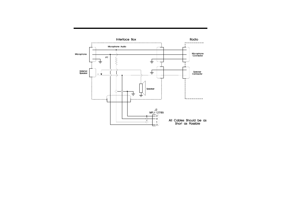
MFJ-1278B MULTI-MODE RADIO INTERFACING
Fig. 3-7 External Interface Box
If you built the external interface box as in Fig.3-7, then follow this procedure to adjust R(s).
1.
Install JMP J on the MFJ-1278B PC board.
2.
Temporarily solder a variable resistor in place of R(s) Fig. 3-7. The maximum value of
this resistor can be determined by experiment. However, a 500K resistor should be
adequate most cases. Connect your MFJ-1278B to the radio. Connect the microphone
to the radio, or to the interface box if one is being used. Connect the radio to a dummy
load and listen to the transmission with another nearby radio. Adjust R(s) for proper
modulation as the next sections describe.