Read/write function block data – Eaton Electrical PROFIBUS-DP EZ204-DP User Manual
Page 127
Read/write function block data
For more information visit: www.EatonElectrical.com
MN05013001E
123
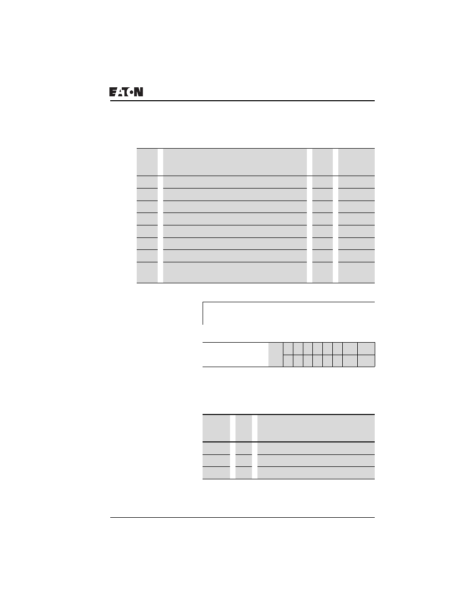
Table 52: Operand overview
Table 53: Index 0: Bit IO
Table 54: Index 1 - Mode
Index
(hex)
Operand
Read
Write
00
Bit IO, J Table 53
×
01
Mode, J Table 54
×
02
Comparison value 1
I1
×
c
1
03
Gain factor for I1 (I1 = F1 χ value)
F1
×
c
1
04
Comparison value 2
I2
×
c
1
05
Gain factor for I2 (I2 = F2 χ value)
F2
×
c
1
06
Offset for value I1
OS
×
c
1
07
Switching hysteresis for value I2 (the value of HY
is for both positive and negative hysteresis.)
HY
×
c
1
1) The value can only be written if it is assigned to a constant in the program.
J
The data for index 2 to 7 is transferred as a 32-bit value in
Intel format (Data 1 – Low Byte to Data 4 – High Byte).
Bit 7 6 5 4 3 2 1
0
FB output Data 3
– – – – – – CY
1
Q1
2
1) Status 1 if the value range is exceeded
2) Status 1 if the condition is fulfilled (e.g. I1 < I2 with LT mode)
Data 1
(hex)
00
LT
Less than (I1 < I2)
01
EQ
Equal to (I1 = IGT)
02
GT
Greater than (I1 > I2)