Rear – Sony ZRD-B12A Micro LED Video Wall Modular Display User Manual
Page 10
10
POWER indicator
Indicates the power status of the Display
Controller.
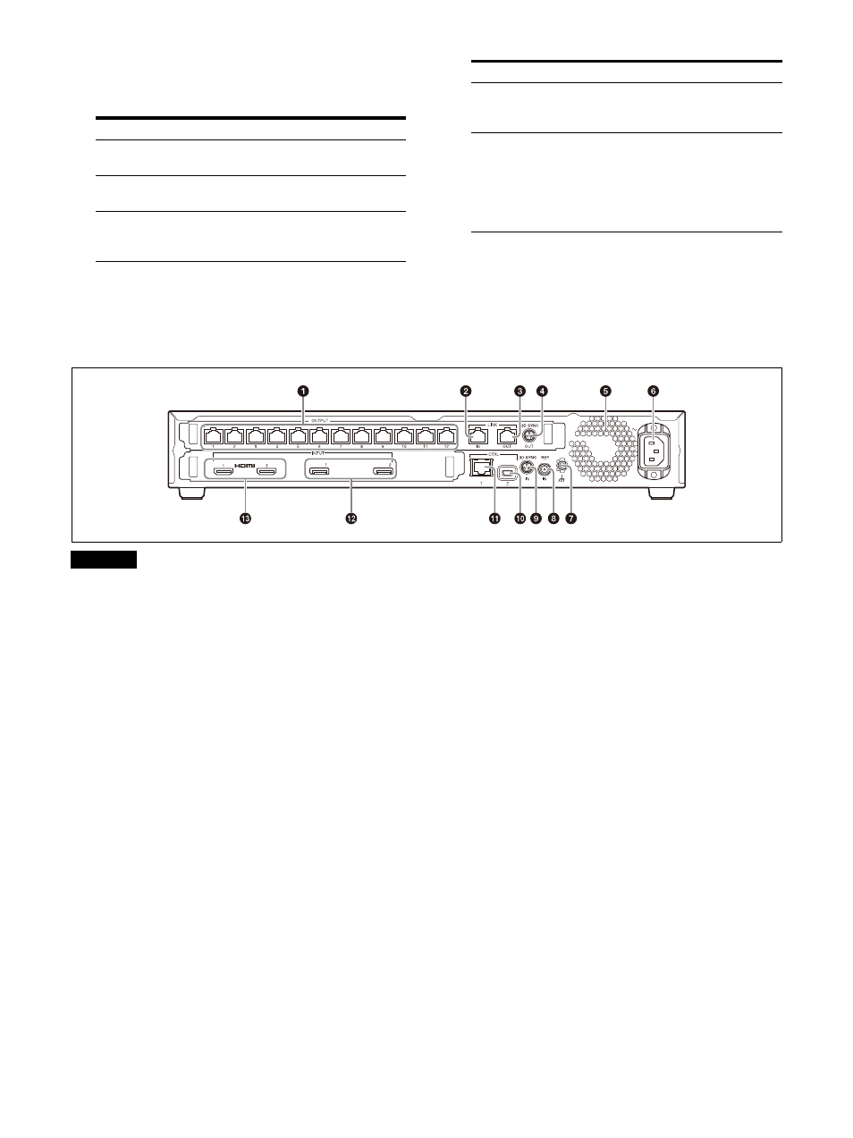
Rear
Do not connect the OUTPUT, LINK IN, and LINK
OUT connectors to a hub. The input/output
signals for these connectors are unique to the
product and are not Ethernet signals. In
particular, be aware that connecting these
connectors to a PoE injector hub may result in
damage to the product.
OUTPUT connectors 1 to 12 (RJ-45)
Use a Category 7 cable (not supplied) to
connect this connector to the IN (cabinet
input) connector on the Display Cabinet you
want to control (first Display Cabinet in the
daisy-chain connection).
LINK IN connector (RJ-45)
Use this when using multiple Display
Controllers to control the Display Cabinets.
Use a Category 7 cable (not supplied) to
connect this connector to the LINK OUT
connector on the Display Controller you want
to link.
LINK OUT connector (RJ-45)
Use this when using multiple Display
Controllers to control the Display Cabinets.
Use a Category 7 cable (not supplied) to
connect this connector to the LINK IN
connector on the Display Controller you want
to link.
3D SYNC OUT connector (mini-DIN, 3-pin)
Outputs 3D sync signals.
Exhaust vent/fan
Do not block the exhaust vent, as doing so
will result in interior heat buildup which may
result in fire or malfunction.
IN (AC power input) connector
Use a power cord (not supplied) to connect
this connector to the circuit breaker.
Indicator
Status
Off
The Display Controller is
turned off.
Lit orange
The Display Controller is in
standby mode.
Lit green
The Display Controller is
turned on (normal operating
status).
Blinking green
The Display Controller is
starting up or shutting
down.
Lit red
The forced standby mode
has been entered.
For details, see “Entering
the forced standby
mode” (page 28) in the
“Troubleshooting.”
Indicator
Status
Caution