Figure 22, Customer cable entry points, Electrical connections 32 – Emerson Liebert XDF User Manual
Page 38
Electrical Connections
32
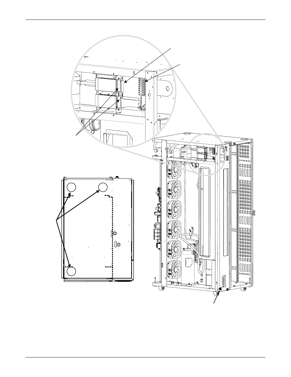
Figure 22 Customer electrical connections and cable entry points—water/glycol cooled units
Move plate to back panel for alternate
power cord routing (see also Figure 23)
Customer Connections:
37 & 38 Remote Shutdown Contacts
75 & 76 Customer Alarm Contacts
94 & 95 Customer Warning Contacts
Ambient
Temperature/Humidity
Sensor
Communication
Card Slots (cards
provided when
option is selected)
(Contacts listed from top to bottom;
All contacts rated 1A, 24VAC maximum)
RE
T
UR
N
(O
U
T
)
SU
PPL
Y
(IN)
Customer
Cable Entry
Points
TOP VIEW
Rear
Dashed line
delineates
equipment
compartment
Power connection locations
(refer to Figure 21 for details)