ProSoft Technology MVI69-ADM User Manual
Page 44
Understanding the MVI-ADM API
MVI-ADM ♦ 'C' Programmable
Developer's Guide
'C' Programmable Application Development Module
Page 44 of 342
ProSoft Technology, Inc.
February 20, 2013
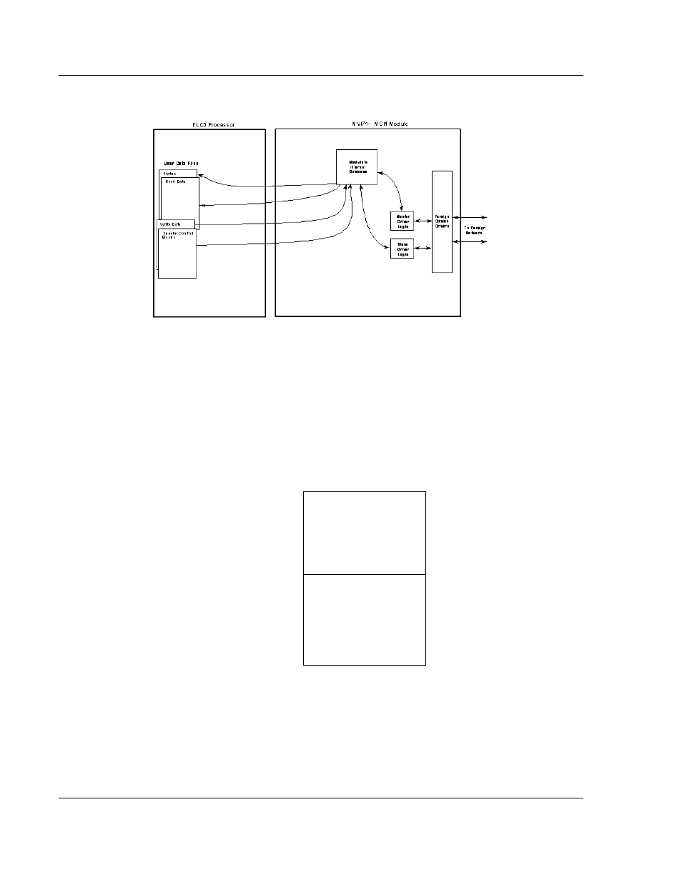
Side-Connect
When the side connect interface is used, data is transferred directly between the
processor and the module. The module's program interfaces directly to the set of
user data files established in the PLC to pass all data between the two devices.
No ladder logic is required for data transfer, only the establishment of the data
files.
All data transferred between the module and the processor over the backplane is
through the input and output images. Ladder logic must be written in the PLC
processor to interface the input and output image data with data defined in the
Controller Tags. All data used by the module is stored in its internal database.
Module’s Internal Database Structure
5000 registers for user data
0
Register Data
4999
3000 words of configuration and
status data
5000
Status and Config
7999
Data contained in this database is paged through the input and output images by
coordination of the PLC ladder logic and the MVI71-ADM module's program. Up
to 60 words of data can be transferred from the module to the processor at a
time. Up to 60 words of data can be transferred from the processor to the
module. Each image has a defined structure depending on the data content and
the function of the data transfer.