ProSoft Technology MVI69-ADM User Manual
Page 31
MVI-ADM ♦ 'C' Programmable
Understanding the MVI-ADM API
'C' Programmable Application Development Module
Developer's Guide
ProSoft Technology, Inc.
Page 31 of 342
February 20, 2013
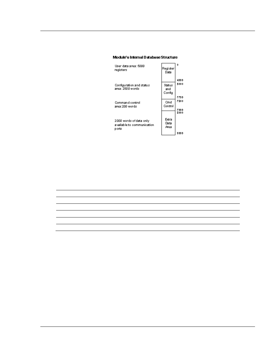
All data used by the module is stored in its internal database. The following
illustration shows the layout of the database:
User data contained in this database is continuously read from the M1 file. The
configuration data is only updated in the M1 file after each configuration request
by the module to the SLC. All data in the M1 file is available to devices on the
foreign networks. This permits data to be transferred from these devices to the
SLC using the user data area. Additionally, remote devices can alter the
module's configuration, read the status data and issue control commands. Block
identification codes define specific functions to the module.
The block identification codes used by the module are listed below:
Block Range
Descriptions
9000
Configuration request from module
9001
Configuration ready from controller
9997
Write configuration to controller
9998
Warm-boot control block
9999
Cold-boot control block
Each block has a defined structure depending on the data content and the
function of the data transfer as defined in the following topics.
Normal Data Transfer
This version of the module provides for direct access to the data in the module.
All data related to the module is stored in the module’s M1 file. To read data from
the module, use the COP instruction to copy data from the module’s M1 file to a
user data file. To write data to the module, use the COP instruction to copy data
from a user file to the module’s M1 file. Registers 0 to 4999 should be used for
user data. All other registers are reserved for other module functions.