5 wiring the fault alarm contact – PLANET IVC-2002 User Manual
Page 20
20
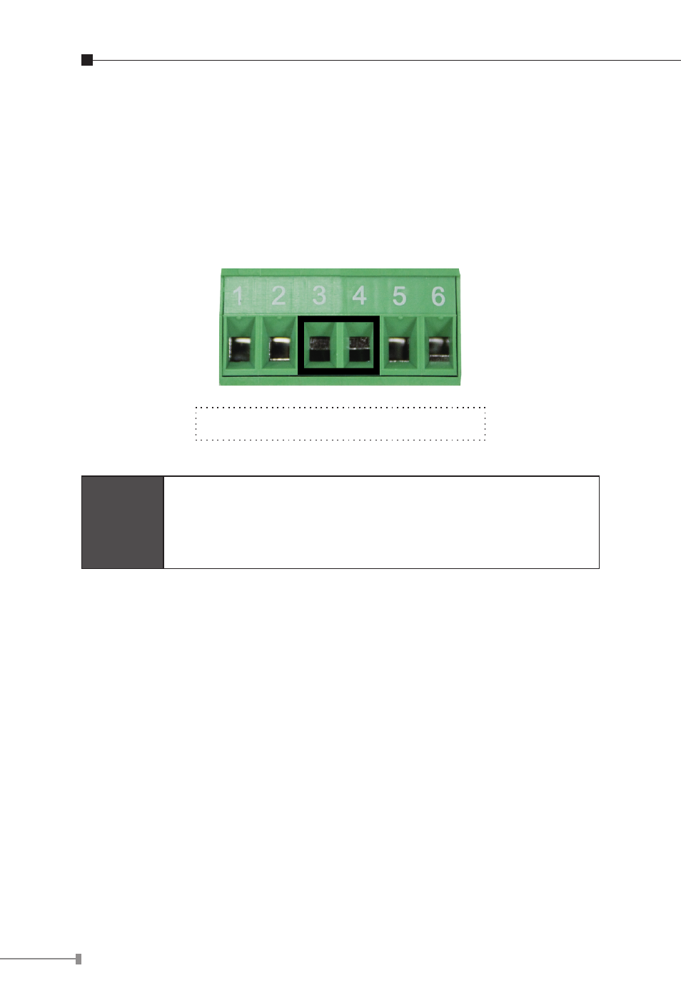
3.5 Wiring the Fault Alarm Contact
The fault alarm contacts are in the middle of the terminal block
connector as the picture shows below. Inserting the wires, the
Industrial Ethernet Extender will detect the fault status of the power
failure and then forms an open circuit. The following illustration shows
an application example for wiring the fault alarm contacts.
Insert the wires into the fault alarm contacts
Note
1. The wire gauge for the terminal block should be in
the range between 12 ~ 24 AWG.
2. Alarm relay circuit accepts up to 30V, max. 3A
currents.
See also other documents in the category PLANET Routers:
- FNSW-1601 (2 pages)
- FNSW-1601 (2 pages)
- FGSW-1816HPS (2 pages)
- FGSW-1816HPS (110 pages)
- FGSW-1816HPS (105 pages)
- WGSD-10020HP (16 pages)
- GS-5220-16S8CR (432 pages)
- FGSD-1022P (226 pages)
- FGSD-1022P (12 pages)
- FGSD-910P (28 pages)
- FGSW-1602RS (30 pages)
- FGSW-2402S (39 pages)
- FGSW-2620PVS (50 pages)
- FGSW-2624SF (2 pages)
- FGSW-2620VM (213 pages)
- FGSW-2624SF (2 pages)
- FGSW-2620VM (96 pages)
- FGSW-2620VM (2 pages)
- FGSW-2620 (2 pages)
- FGSW-2620CS (81 pages)
- FGSW-2620CS (2 pages)
- FGSW-2620CS (80 pages)
- FGSW-2620CS (2 pages)
- FGSW-4840S (263 pages)
- FGSW-2840 (2 pages)
- FGSW-4840S (2 pages)
- FGSW-4840S (38 pages)
- FNSW-1600P (20 pages)
- FNSW-1600S (33 pages)
- FNSW-2400PS (70 pages)
- FNSW-2400PS (2 pages)
- FNSW-1602S (43 pages)
- FNSW-2402S (39 pages)
- FNSW-4800 (2 pages)
- FNSW-2401CS (38 pages)
- FSD-1604 (12 pages)
- FSD-2405 (18 pages)
- FSD-1606 (2 pages)
- FSD-803 (2 pages)
- FSD-803 (2 pages)
- FSD-504HP (2 pages)
- FSD-805ST (20 pages)
- FSD-804P (21 pages)
- FSD-808P (22 pages)
- FSD-808P (20 pages)