2 the upper panel – PLANET IVC-2002 User Manual
Page 14
14
Band Plan
l
t User can switch the Band Plan either Symmetric or Asymmetric
by their own. When Symmetric is selected that provides better
upstream performance, when Asymmetric is selected that provides
better downstream performance. Refer to table above for details.
Target SNR (Signal Noise Ratio) Margin
l
t When fixed SNR margin is selected, the system will maintain the
SNR margin at 9 dB across all usable loop length.
Note
1. By default setting, the four DIP switch at “ON”
position and operate as “Slave”. For operate as
“Master”, please adjust the DIP 1 switch to “OFF”
position. Adjust other DIP switch setting to fill
different network application demand.
2. Link type: both of IVC-2002 must switch to the
same position, otherwise, it may cause unstable. For
example, if want to connect both of IVC-2002 through
BNC cable, the Master (CO) and Slave (CPE) must
switch the DIP-2 at BNC mode.
Please power off the Industrial Ethernet Extender before making any
transmission mode adjustment.
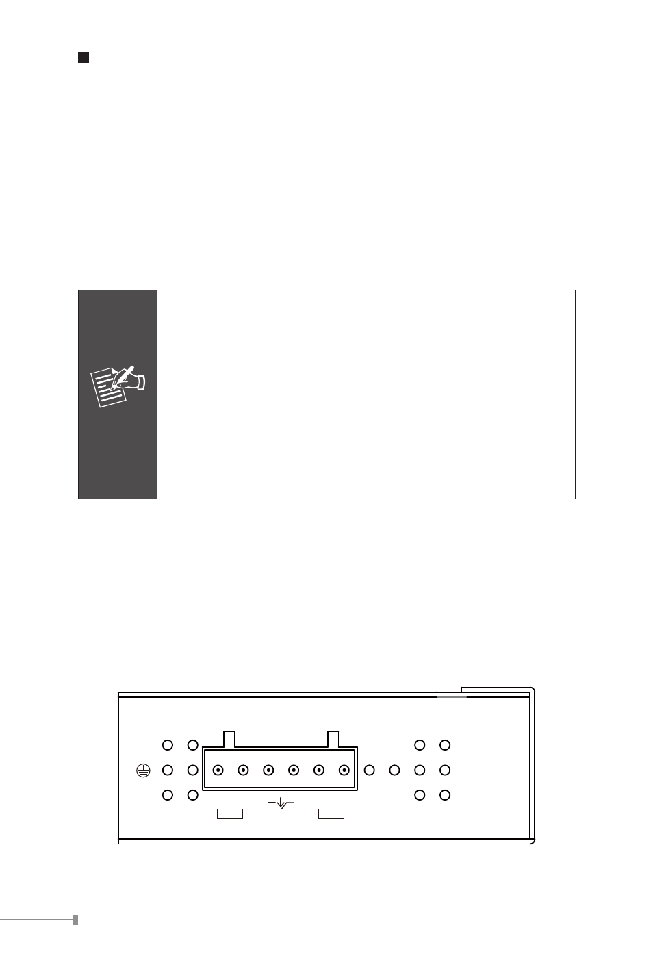
2.2 The Upper Panel
The upper panel of the Industrial Ethernet Extender consist one
terminal block connector within two DC power inputs. Figure 2-2 shows
the upper panel of the Industrial Ethernet Extender.
Input
DC12~48V
V1- V1+
V2- V2+
PWR1
PWR2
Fault
Figure 2-2 Industrial Ethernet Extender upper Panel.