2 poe status – PLANET FGSD-1008HPS User Manual
Page 88
User’s Manual of FGSD / FGSW Web Smart PoE Switch
88
4.10.2 PoE Status
In a power over Ethernet system, operating power is applied from a power source (PSU-power supply unit) over the LAN
infrastructure to powered devices (PDs), which are connected to ports. Under some conditions, the total output power required
by PDs can exceed the maximum available power provided by the PSU. The system may a prior be planed with a PSU capable
of supplying less power than the total potential power consumption of all the PoE ports in the system. In order to maintain the
majority of ports active, power management is implemented.
The PSU input power consumption is monitored by measuring voltage and current .The input power consumption is equal to the
system’s aggregated power consumption .The power management concept allows all ports to be active and activates additional
ports, as long as the aggregated power of the system is lower than the power level at which additional PDs cannot be
connected .When this value is exceeded, ports will be deactivated, according to user-defined priorities. The power budget is
managed according to the following user-definable parameters: maximum available power, ports priority, maximum allowable
power per port.
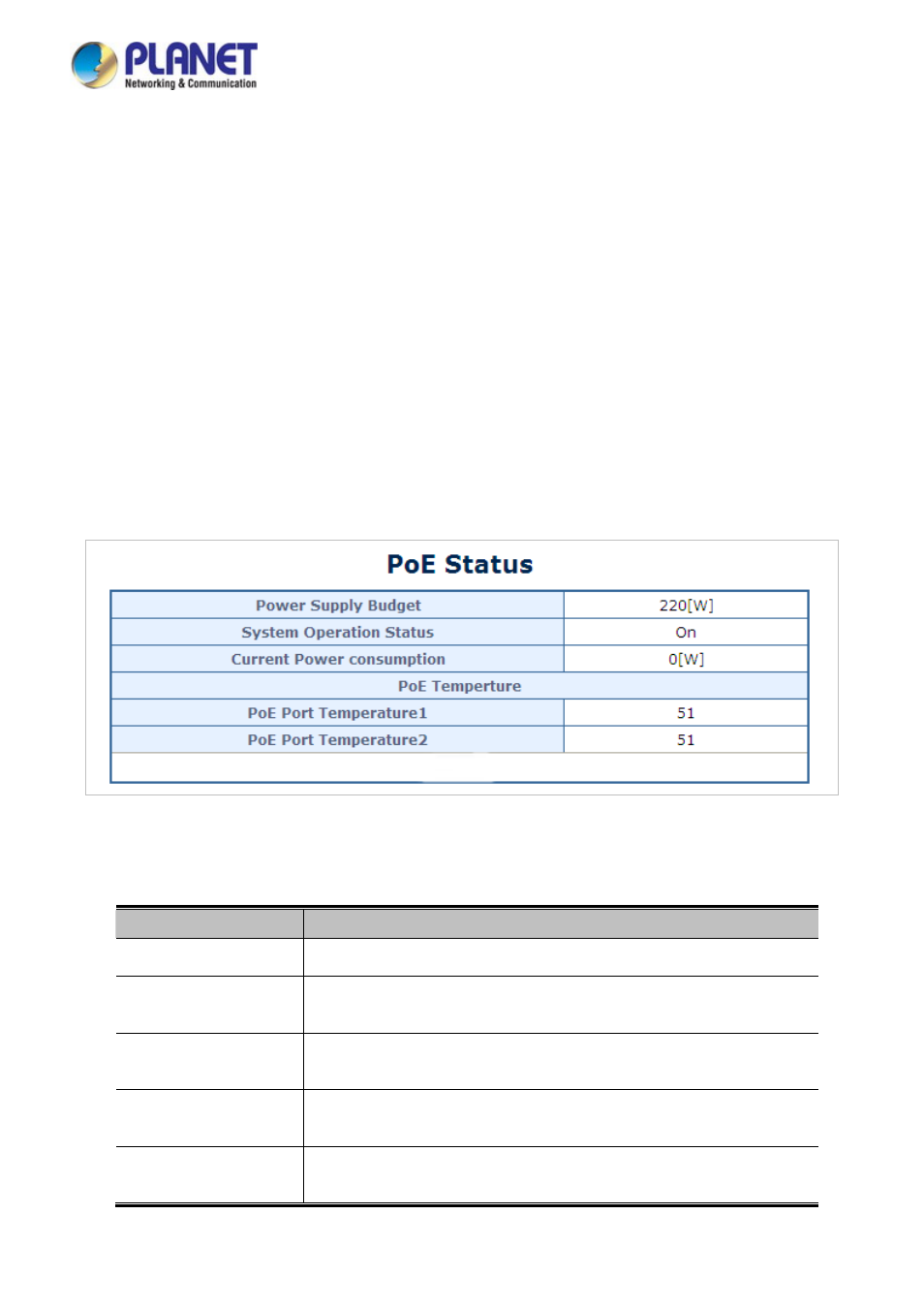
This section allows the user to see the current status of PoE; screen in
Figure 4-10-1
appears.
Figure 4-10-1
PoE Status Screenshot
The page includes the following fields:
Object
Description
Power Supply Budget
Configure the total watts usage of PoE Switch.
System Operation
Status
Display the current System Operation Status.
Current Power
Consumption
Display the current Current Power Consumption.
PoE Port 1~8
Temperature
Display the current operating temperature of PoE chip unit 1.
The unit 1 is in charge of PoE Port-1~Port-8
PoE Port 9~16
Temperature
Display the current operating temperature of PoE chip unit 2.
The unit 1 is in charge of PoE Port-9~Port-16