Level shifting/ttl interface with shunt led drive, Description, Performance of circuit – Avago Technologies ACPL-224-500E User Manual
Page 20: Benefits, Alternative avago parts
AV02-4387EN
17
Avago Technologies
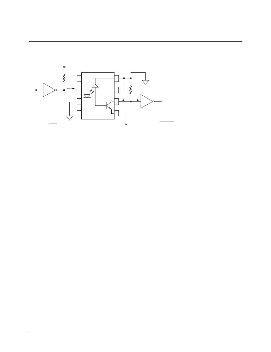
Description
The above circuit shows how a 0 to 5
V logic signal can be level shifted to a
-15 to 0 V signal. The circuit can safely
be used for level shifting up to ±800
V. The circuit uses an open collector
output logic gate, the 74LS405, to
drive the LED of the HCPL-4502/3
optocoupler. The HCPL-4502/3 also
has an open-collector output. The
designer chooses R
IN
to agree with
the equation shown in the schemat-
ic. This equation sets the value of the
optocoupler LED forward current.
The output of the HCPL-4502/3 re-
quires a pull-up resistor, R
L
. The cur-
rent-transfer ratio (CTR) of the opto-
coupler determines the maximum
amount of current the optocoupler
output can sink while maintaining
the output voltage (between pins 5
and 6) of 0.5 V or less.
Performance of Circuit
• Maximum optocoupler propa-
gation delay: 2 µs (refer to al-
ternative Avago parts for lower
propagation delays)
• Typical signaling rate: dc to 1 MBd
(refer to alternative Avago parts
for higher speeds)
• Typical optocoupler LED drive
current: 10 to 16 mA
• Maximum output supply voltage
(pins 8-5): 30 V
• Minimum CMR: 15 kV/µs slew
rate, 1500 V peak
Benefits
• Reduces transient immunity
problems
• Convenient way of replacing
pulse transformer for high-volt-
age level shifting
Alternative Avago Parts
1) HCPL-07XX, HCPL-2730/1, HCPL-
4701, 6N138/9, HCNW138/9 Low
Input Current Optocouplers
2) HCPL-55XX Hermetically Sealed
High Speed Optocoupler
3) HCPL-0710 SO-8 High Speed
CMOS Optocoupler
4) HCPL-250L/260L/270L, HC-
PL-050L/060L/070L 3.3V Opto-
couplers
Level Shifting/TTL Interface with Shunt LED Drive
Digital Logic Interface/Level Shifting Applications
I
F
7
5
6
8
2
3
4
1
NOTE: FOR BEST CMR PERFORMANCE, CONNECT PIN 7 TO PIN 8.
IN
R
74LS05
IN
R = 5 - V
F
HCPL-4502/3
+5 V
I
F
L
R
OL
V
-15 V
I
O
(min) = I
F
• CTR (min)
R
L
(min) = 15 – V
OL
I
O
(min) + I
IL
I
IL
I
O
V
IN
V
OUT
- ACPL-227-500E ACPL-244-500E ACPL-247-500E ACPL-785J-000E ACPL-C780-000E ACPL-C784-000E ACPL-C78A-000E HCPL-0201 HCPL-0211 HCPL-0300 HCPL-0302 HCPL-0314 HCPL-0370 HCPL-0452 HCPL-0453 HCPL-0454 HCPL-0466 HCPL-0500 HCPL-0501 HCPL-050L HCPL-0530 HCPL-0531 HCPL-0534 HCPL-053L HCPL-0600 HCPL-0601 HCPL-060L HCPL-0611 HCPL-061A HCPL-061N HCPL-0630 HCPL-0631 HCPL-063A HCPL-063L HCPL-063N HCPL-0661 HCPL-0700 HCPL-0701 HCPL-0708 HCPL-070A HCPL-070L HCPL-0710 HCPL-0720 HCPL-0721 HCPL-0723 HCPL-0730 HCPL-0731 HCPL-0738 HCPL-073A HCPL-073L HCPL-0872 HCPL-0900 HCPL-090J HCPL-091J HCPL-092J HCPL-0930 HCPL-0931 HCPL-177K HCPL-177k#200 HCPL-177K-100 HCPL-177K-300 HCPL-177K-600 HCPL-181-000E HCPL-1930 HCPL-1930#100 HCPL-1930#200 HCPL-1930#300 HCPL-1931 HCPL-1931#100 HCPL-1931#200 HCPL-1931#300 HCPL-193K HCPL-193K#200 HCPL-2200 HCPL-2201 HCPL-2202 HCPL-2211 HCPL-2212 HCPL-2219 HCPL-2231 HCPL-2232 HCPL-2300 HCPL-2400 HCPL-2430 HCPL-2502 HCPL-2503 HCPL-250L HCPL-2530 HCPL-2531 HCPL-2533 HCPL-253L HCPL-257K HCPL-257K#200 HCPL-257K-100 HCPL-257K-300 HCPL-2601 HCPL-2602 HCPL-260L HCPL-2611 HCPL-2612 HCPL-261A HCPL-261N HCPL-2630 HCPL-2631 HCPL-263A HCPL-263L HCPL-263N HCPL-268K HCPL-268K#200 HCPL-268K-100 HCPL-268K-300 HCPL-270L HCPL-2730 HCPL-2731 HCPL-273L HCPL-3020 HCPL-3120 HCPL-3140 HCPL-314J HCPL-3150 HCPL-315J HCPL-316J HCPL-3180 HCPL-354-000E HCPL-3700 HCPL-3760 HCPL-4100 HCPL-4200 HCPL-4502 HCPL-4503 HCPL-4504 HCPL-4506 HCPL-4534 HCPL-4562 HCPL-4661 HCPL-4701 HCPL-4731 HCPL-5120 HCPL-5120-100 HCPL-5120-200 HCPL-5120-300 HCPL-5121 HCPL-5121-100 HCPL-5121-200 HCPL-5121-300 HCPL-5150 HCPL-5150-100 HCPL-5150-200 HCPL-5150-300 HCPL-5151 HCPL-5151-100 HCPL-5151-200 HCPL-5151-300 HCPL-5200 HCPL-5200#100 HCPL-5200#200 HCPL-5200#300 HCPL-5201 HCPL-5201#100 HCPL-5201#200 HCPL-5201#300 HCPL-520K HCPL-520K#200 HCPL-520K-100 HCPL-520K-300 HCPL-5230 HCPL-5230#100 HCPL-5230#200 HCPL-5230#300 HCPL-5231 HCPL-5231#100 HCPL-5231#200 HCPL-5231#300 HCPL-523K HCPL-523K#200 HCPL-523K-100 HCPL-523K-300 HCPL-5300 HCPL-5300#100 HCPL-5300#200 HCPL-5300#300 HCPL-5301 HCPL-5301#100 HCPL-5301#200 HCPL-5301#300 HCPL-530K HCPL-530K#200 HCPL-5400 HCPL-54#100 HCPL-54#200 HCPL-54#300 HCPL-5401 HCPL-5401#100 HCPL-5401#200 HCPL-5401#300 HCPL-540K HCPL-540K#200 HCPL-540K-100 HCPL-540K-300 HCPL-5430 HCPL-5430#100 HCPL-5430#200 HCPL-5430#300 HCPL-5431 HCPL-5431#100 HCPL-5431#200 HCPL-5431#300 HCPL-543K HCPL-543K#200 HCPL-543K-100 HCPL-543K-300 HCPL-5500 HCPL-5500#100 HCPL-5500#200 HCPL-5500#300 HCPL-5501 HCPL-5501#100 HCPL-5501#200 HCPL-5501#300 HCPL-550K HCPL-550K#200 HCPL-550K-100 HCPL-550K-300 HCPL-5530 HCPL-5530#100 HCPL-5530#200 HCPL-5530#300 HCPL-5531 HCPL-5531#100 HCPL-5531#200 HCPL-5531#300 HCPL-553K HCPL-553K#200 HCPL-553K#300 HCPL-553K-100 HCPL-5600 HCPL-5600#100 HCPL-5600#200 HCPL-5600#300 HCPL-5601 HCPL-5601#100 HCPL-5601#200 HCPL-5601#300 HCPL-560K HCPL-560K#200 HCPL-560K-300 HCPL-560K-100 HCPL-5630 HCPL-5630#100 HCPL-5630#200 HCPL-5630#300 HCPL-5631 HCPL-5631#100 HCPL-5631#200 HCPL-5631#300 HCPL-563K HCPL-563K#200 HCPL-563K-100 HCPL-563K-300 HCPL-5650 HCPL-5650#200 HCPL-5651 HCPL-5651#200 HCPL-5700 HCPL-5700#100 HCPL-5700#200 HCPL-5700#300 HCPL-5701 HCPL-5701#100 HCPL-5701#200 HCPL-5701#300 HCPL-570K HCPL-570K#200 HCPL-570K#300 HCPL-570K-100 HCPL-5730 HCPL-5730#100 HCPL-5730#200 HCPL-5730#300 HCPL-5731 HCPL-5731#100 HCPL-5731#200 HCPL-5731#300 HCPL-573K HCPL-573K#200 HCPL-573K#300 HCPL-573K-100 HCPL-5760 HCPL-5760#100 HCPL-5760#200 HCPL-5760#300 HCPL-5761 HCPL-5761#100 HCPL-5761#200 HCPL-5761#300 HCPL-576K HCPL-576K#200 HCPL-576K-100 HCPL-6230 HCPL-6231 HCPL-623K HCPL-6250 HCPL-6251 HCPL-625K HCPL-6430 HCPL-6431 HCPL-643K HCPL-6530 HCPL-6531 HCPL-653K HCPL-6550 HCPL-6551 HCPL-655K HCPL-6630 HCPL-6631 HCPL-663K HCPL-6650 HCPL-6651 HCPL-665K HCPL-6730 HCPL-6731 HCPL-673K HCPL-6750 HCPL-6751 HCPL-675K HCPL-7510 HCPL-7520 HCPL-7560 HCPL-7710 HCPL-7720 HCPL-7721 HCPL-7723 HCPL-7800 HCPL-7800A HCPL-7840 HCPL-7850 HCPL-7850#100 HCPL-7850#200 HCPL-7850#300 HCPL-7851 HCPL-7851#100 HCPL-7851#200 HCPL-7851#300 HCPL-7860 HCPL-786J HCPL-788J HCPL-814-000E HCPL-817-000E HCPL-9000 HCPL-900J HCPL-901J HCPL-902J HCPL-9030 HCPL-9031 HCPL-J312 HCPL-J314 HCPL-J454 HCPL-J456 HCPL-M452 HCPL-M453 HCPL-M454 HCPL-M456 HCPL-M600 HCPL-M601 HCPL-M611 HCPL-M700 HCPL-M701 HCPL-T250 HCPL-T251