6 remote on-off (-1urx and -1ury models only), Remote on-off (-1urx and -1ury models only) -23, R. 2.6 – KEPCO RA 19-1U Operator Manual User Manual
Page 39
RA 19-1U 020413
2-23
2.6
REMOTE ON-OFF (-1URX AND -1URY MODELS ONLY)
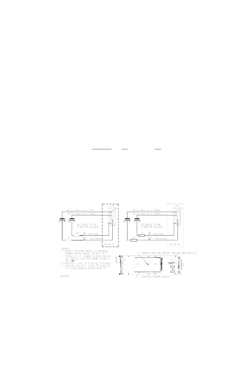
Power switch of HSF must be set to on. Use designated ±RC pins of applicable I/O connector
(see below) to set specified output on or off. See Figure 2-17 for typical configuration. Note that
when ±RC are used, only the normally-closed Alarm (open on failure) is available for use. Con-
tact Kepco if isolation between alarm and remote on-off is required.
• Output OFF requires no voltage, or short circuit, or 0 to 0.8V across ±RC pins of I/O con-
nector.
• Output ON requires 4.5 to 12.5V (or 12.5 to 24.5V through 1.5K Ohms) across ±RC pins
of I/O connector.
To reverse the polarity of the on-off voltage (where output ON requires no voltage, or short cir-
cuit, or 0 to 0.8V across ±RC pins of I/O connector), contact Kepco.
I/O connector pins designated for use for remote on-off are as follows:
I/O Connector
+RC
–RC
Slot 1
PS1, PS2
Pin 11
Pin 15
Slot 2
PS1, PS2
Pin 9
Pin 13
Slot 3
PS3, PS4
Pin 11
Pin 15
Slot 4
PS3, PS4
Pin 9
Pin 13
CAUTION:
–RC is also the –V output of the HSF power supply.
For -1URY models, –RC may also be used for +IMON.
+RC is also the Alarm Common of the HSF power supply.
±RC pins are NOT isolated from DC output pins.
NOTE: ±RC pins of I/O connector are isolated from AC input pins.
FIGURE 2-17. USING REMOTE ON-OFF (TYPICAL), -1URX AND -1URY MODELS ONLY