1 establishing key positions, Figure 2-1. ra 19-1u rack adapter keying, 4 slot configuration – KEPCO RA 19-1U Operator Manual User Manual
Page 18: Establishing key positions -2, Slot configuration -2, Ra 19-1u rack adapter keying -2
2-2
RA 19-1U 020413
2.3.1
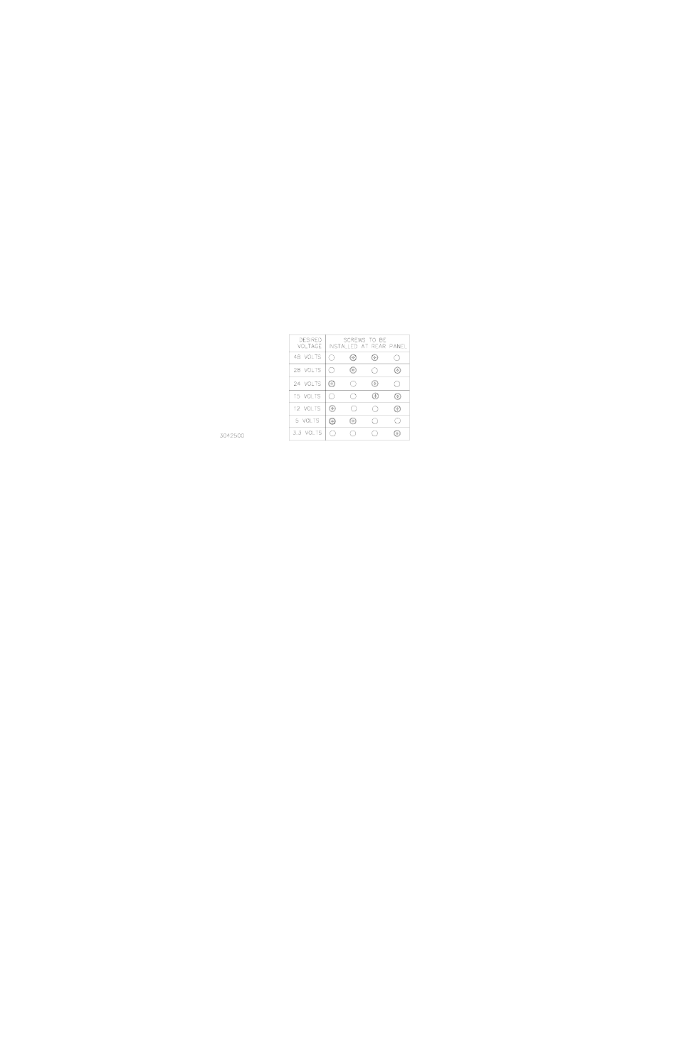
ESTABLISHING KEY POSITIONS
To establish the keying of any position, simply install the 4-40 x 0.75 in. thread-forming screws
(Kepco P/N 101-0480) into the corresponding holes as indicated in Figure 2-1. DO NOT OVER-
TIGHTEN these screws (max torque 5 in.-lbs. (0.6 N x m). DO NOT ALTER THE KEYING AT
THE POWER SUPPLY.
FIGURE 2-1. RA 19-1U RACK ADAPTER KEYING
2.4
SLOT CONFIGURATION
Configuring slots of the rack adapter for independent, parallel or series operation is accom-
plished either by means of DIP switches mounted on the rear panel associated with each slot
(see Figure 1-3), or externally by connecting the appropriate pins of the associated I/O mating
connector. DIP switch functions are explained in Table 2-2.
Slot configuration requires the following selection:
1. Select independent (PAR. 2.4.1), parallel (PAR. 2.4.2), or series (PAR. 2.4.3) operation.
2. Select local or remote sensing; PAR. 2.4.1 (independent), 2.4.2, (parallel) or 2.4.3, (series).
3. Optional: Select close-on-failure or open-on-failure alarm (PAR. 2.4.4).
4. Current Monitoring (Models -1URC and -1URY only, see PAR. 2.5).
5. Remote On-Off (Models -1URX and -1URY only, see PAR. 2.6).