KEPCO RA 19-1U Operator Manual User Manual
Page 21
RA 19-1U 020413
2-5
2.4.1.2
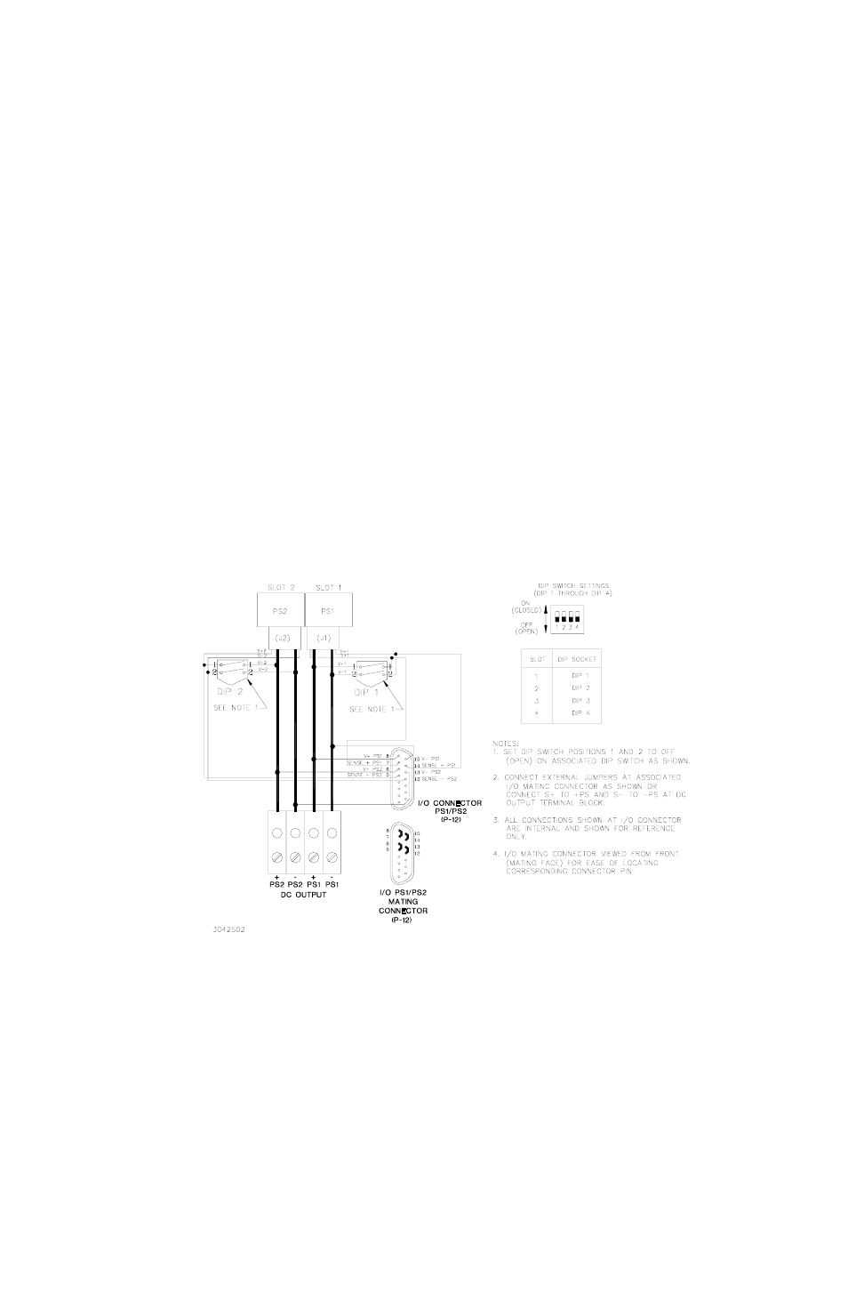
INDEPENDENT OPERATION - LOCAL SENSING USING EXTERNAL WIRING
To configure a slot for local sensing using external wiring, first set rear panel DIP switch posi-
tions 1 and 2 of the DIP switches associated with that slot to OFF (open).
External local sensing is accomplished by connecting (V+) to (S+) and (V–) to (S–). This can be
done at either the mating I/O connector supplied (see Table 2-1) or at the DC OUTPUT terminal
block. See Figure 1-3 for DIP socket locations. Figure 1-3 illustrates I/O connector pin assign-
ments. Figure 2-3 illustrates local sensing of PS1 and PS2 using external jumpers connected to
the I/O mating connector.
NOTE: The rear panel DIP switch settings established at the factory for positions 1 and 2 of
the associated DIP switch MUST be changed to OFF (open) if this option is chosen.
Positions 3 and 4 (connecting sense lines in parallel) and Position 5 (current share) must be set
to OFF. Configure Positions 6, 7, and 8 (alarms) per PAR. 2.4.4.
FIGURE 2-3. INDEPENDENT OPERATION, LOCAL SENSING FOR PS1 AND PS2 USING
EXTERNAL JUMPERS AT I/O MATING CONNECTOR, SIMPLIFIED DIAGRAM
- ABC-DM SERIES (96 pages)
- ATE (all models) QUICK START GUIDE (8 pages)
- SN 488-D (16 pages)
- SN 488-D (94 pages)
- SN 488-D (14 pages)
- BHK-MG 200W (Full Rack) Series (152 pages)
- BHK-MG 40W (Half Rack) Series (148 pages)
- BIT 232 (72 pages)
- BIT 4882 (56 pages)
- BIT 4886 Quick Start Guide (4 pages)
- BIT 4886 Operator Manual (92 pages)
- BOP 100W, 200W, 400W (M, D) Quick Start Guide (8 pages)
- BOP 20-5ML Modification Sheet (1 page)
- BOP 20-10MC Modification Sheet (2 pages)
- BOP 36-6MC Modification Sheet (2 pages)
- BOP 100-2MC Modification Sheet (2 pages)
- BOP 50-4MC Modification Sheet (2 pages)
- BOP 100-2ML Modification Sheet (2 pages)
- BOP 72-3ML Modification Sheet (2 pages)
- BOP 50-4ML Modification Sheet (2 pages)
- BOP 36-6ML Modification Sheet (2 pages)
- BOP 20-10ML Modification Sheet (2 pages)
- BOP 72-6MC Modification Sheet (2 pages)
- BOP 36-12MC Modification Sheet (2 pages)
- BOP 20-20MC Modification Sheet (2 pages)
- BOP 100-4ML Modification Sheet (2 pages)
- BOP 72-6ML Modification Sheet (2 pages)
- BOP 50-8ML Modification Sheet (2 pages)
- BOP 36-12ML Modification Sheet (2 pages)
- BOP 20-20ML Modification Sheet (2 pages)
- BOP 1KW-MG Quick Start Guide (16 pages)
- BOP 1KW-MG Quick Reference Guide (2 pages)
- BOP 1KW-MG Operator Manual, Firmware Ver.4.12 and higher (196 pages)
- BOP 1KW-MG Operator Manual, Firmware Ver.4.08 to 4.11 (194 pages)
- BOP 1KW-MG Operator Manual, Firmware Ver.3.05 to 4.07 (194 pages)
- BOP 1KW-MG Operator Manual, Firmware Ver.2.48 to 3.04 (188 pages)
- BOP 1KW-MG Operator Manual, Firmware Ver.2.38 to 2.47 (188 pages)
- BOP 1KW-MG Operator Manual, Firmware Ver.2.01 to 2.37 (176 pages)
- BOP 1KW as Solar Device Tester Quick Start Guide (3 pages)
- BOP-GL 1KW Quick Start Guide (16 pages)
- BOP-GL 1KW Operator Manual Firmware Ver.3.05 and higher (168 pages)
- BOP-HV (48 pages)
- CA 26 (2 pages)
- CA 27 (2 pages)
- CA 29 (2 pages)